
________________________________________________________________________________
Kubota L245DT, L2350, L2550 - Engine Service and Maintenance
Kubota L235, L245DT, L2350 tractors fitted with D1102 diesel engine.
D1402 engine used in L2550 model.
Kubota L2350, L245DT, L2550, L235 - Diesel
Fuel System
Kubota L235, L245DT, L2350, L2550 tractors are equipped with an inline,
multiple plunger type injection pump, pintle nozzles and glow plugs.
Because of extremely close tolerances and precise requirements of all
diesel components, it is of utmost importance that clean fuel and
careful maintenance be practiced at all times. Unless necessary special
tools are available, service on injectors and injection pump should be
limited of removal, installation and exchange of complete assemblies. It
is impossible to re-calibrate an injection pump or reset an injector
without proper specifications, equipment and training.
Fuel filter
On Kubota D1102, D1402 engines, filter life depends more on careful fuel
system maintenance than it does on hours or conditions of operation.
Necessity for careful filling with clean fuel cannot be over-stressed.
Fuel filter should be renewed after every 400 hours of operation or once
a year, whichever occurs first. Renew filter immediately if water
contamination is discovered or a decrease in engine power is evident.
Air must be bled from system after installing new filter. To bleed air
from fuel system, open fuel shut-off valve and loosen air vent plug on
filter base. When steady stream of fuel appears at vent plug, tighten
plug. Loosen vent plug on fuel injection pump until air-free fuel
appears, then tighten vent plug. If engine fails to start after bleeding
air from filter and pump, loosen high pressure line connections at
injector nozzles. Move throttle to run position and crank engine with
starting motor until fuel appears at loosened injector line fittings.
Tighten fittings and start engine.
Injection pump
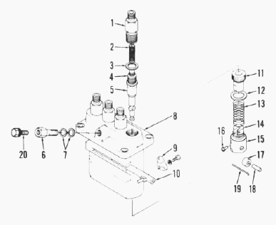
Bosch K type pump is used on all models. The injection pump is a
completely sealed unit and no service work or disassembly other than
that specified should be attempted without necessary special equipment
and training. Timing to engine - On Kubota D1102, D1402 engines, start
of injection should occur at 25° BTDC. To check timing, disconnect fuel
pressure line from injection pump front delivery valve holder. Place
throttle control in maximum fuel position and pull decompressor knob
out. Turn crankshaft slowly until wetness appears at discharge fitting
of injection pump. At this point (beginning of injection), "F1" mark on
flywheel should be aligned with timing check window. If timing requires
adjustment, remove shims between injection pump mounting flange and
cylinder block to advance timing or add shims to retard timing. Adding
or removing one shim will change timing about 1,5 crankshaft degrees
which is about 2.3 mm (3/32 inch) measured on flywheel rim.
Injection pump - Remove and reinstall
To remove injection pump, first thoroughly clean outside of pump and
surrounding area. Shut off fuel and disconnect fuel supply line at
injection pump. Remove high pressure lines leading to injectors. Remove
side access cover or engine stop lever assembly if so equipped. Remove
pump mounting stud nuts, align control rack pin with slot in crankcase
and lift pump assembly from crankcase. Do not lose or damage shim pack
located between pump flange and crankcase. Shims control pump timing and
same number of shims must be reinstalled unless timing is to be changed.
When reinstalling pump, be sure to guide rack control pin into notch in
governor arm and crankcase. Use removed shim pack unless timing is to be
changed. Bleed air from system as previously outlined.
Governor and fuel camshaft
Governor linkage adjustment - High speed adjustment screw and maximum
fuel limit stop should not normally require adjustment unless governor
or injection pump is overhauled. Adjustments should be made by qualified
personnel only. Recommended slow idle speed is 800 to 850 rpm for all
models. Adjustment is made by turning slow idle stop. High idle speed
should be 2750 rpm for L235, L245DT, L2350 and 2950 rpm for L2550. Turn
high idle stop screw for adjustment. Governor assembly can be removed
with the drive gear and fuel camshaft as a unit after removing injection
pump, fuel feed pump (if so equipped), timing gear cover and hydraulic
pump and drive gear from rear end of fuel camshaft. Remove governor
mounting cap screws and withdraw governor and camshaft as an assembly.
To disassemble, remove fork pivot shaft and separate fork levers and
fork lever holder. Remove drive gear retaining ring, then remove gear
and weight assembly using a suitable puller. Governor weight thrust
bearing contains 39 loose balls. Be careful that none are lost when
weight unit is disassembled. Examine cupped race, balls and ball travel
surface on back of gear for furrowing or pitting and renew if damaged.
Inspect fuel camshaft and bearings for scoring, wear or other damage and
renew as necessary. Reassemble by reversing the disassembly procedure.
Be sure hydraulic pump drive gear is installed with hub facing forward.
Bleed air from system, check timing and adjust governor linkage as
previously outlined.
Injector nozzle
Testing and locating faulty nozzle - If engine does not run properly and
a faulty injection nozzle is suspected, check for faulty nozzle as
follows: With engine running at slow idle speed, loosen injector line at
each nozzle in turn to allow fuel to escape at union rather than enter
the cylinder. As in checking spark plugs in a spark ignition engine, the
faulty nozzle is the one that least affects engine operation when its
fuel line is loosened. Remove and test suspected nozzle (or install a
new or reconditioned unit). A complete job of testing and adjusting
injector requires use of special test equipment. Only clean, approved
testing oil should be used in tester tank. Nozzle should be tested for
opening pressure, nozzle leakage and spray pattern. Before conducting
test, operate tester lever until fuel flows, then attach injector. Close
valve to tester gage and pump tester lever a few quick strokes to clear
air from tester and to be sure nozzle valve is not stuck. Nozzle should
open with a buzzing sound and cut off quickly at end of injection.
Open valve to tester gage and operate tester lever slowly while
observing gage reading. Opening pressure should be 13730-14700 kPa
(1990-2135 psi) for all models. Opening pressure is adjusted by changing
thickness of shim. A change in shim thickness of 0.1 mm (0.004 inch)
will change opening pressure approximately 965 kPa (140 psi). To check
for leakage, actuate tester lever slowly to maintain a pressure 1000 kPa
(150 psi) below opening pressure. There should be no accumulation of
fuel at nozzle tip. A slight wetting is allowed after 10 seconds if no
drops are formed. If fuel leakage is evident, injector must be
disassembled, cleaned and overhauled. Spray pattern should be well
atomized and uniform emerging in a straight axis front nozzle tip. If
pattern is wet, ragged or intermittent, nozzle must be overhauled or
renewed.
Injector nozzle - Remove and overhaul
Before removing an injector, throughly clean injector, lines and
surrounding area. Remove high pressure fuel line and disconnect bleed
line. Unscrew nozzle holder from its mounting position on cylinder head.
When reinstalling injector, make sure seating surface in cylinder head
is completely clean and free from carbon buildup. Use a new seal washer
underneath nozzle holder and tighten to 30-49 Nm (22-36 ft.-lbs.)
torque. Hard or sharp tools, emery cloth, wire brush or grinding
compound must never be used. An approved nozzle cleaning kit is
available through a number of specialized sources. Wipe all dirt and
loose carbon from exterior of nozzle assembly. Secure nozzle in a
soft-jawed vise or holding fixture and remove nozzle nut. Carefully
separate parts and place in clean calibrating oil or diesel fuel as they
are removed. Be sure parts from each injector are kept together and
separate from other units.
Clean exterior surfaces with a brass wire brush, soaking in an approved
carbon solvent, if necessary, to loosen hard carbon deposits. Rinse
parts in clean diesel fuel immediately after cleaning to neutralize the
solvent and prevent etching of polished surfaces. Clean nozzle spray
hole from inside using a pointed hardwood stick. Scrape carbon from
pressure chamber using hooked scraper. Clean valve seat using brass
scraper. Reclean all parts by rinsing in clean diesel fuel. Check nozzle
fit by holding nozzle body vertically and lifting needle valve up about
1/3 of its length, then release needle. Needle must slide to its seat by
its own weight. If needle movement is rough or sticky, reclean or renew
nozzle valve assembly as necessary. Reassemble injector while parts are
immersed in diesel fuel to avoid contamination. Make sure pressure
adjusting shim is in place. Tighten nozzle nut to a torque of 59-78 Nm
(44-58 ft.-lbs.). Do not overtighten as distortion may cause nozzle
valve to stick and no amount of overtightening can stop a leak caused by
scratches or dirt. Retest injector as previously outlined.
Glow plug
One glow plug is provided in precombustion chamber of each cylinder. To
check glow plugs, disconnect wiring cable from glow plug terminal, then
connect an ohmmeter across glow plug terminal and body. Resistance
should be approximately 1.5 ohms. If resistance is zero ohms, glow plug
is shorted. If resistance is infinite, an open circuit exists in glow
plug.
Kubota L2350, L245DT, L2550, L235 - Cooling
System
Kubota L235, L245DT, L2350, L2550 use a pressurized cooling system which
raises coolant boiling point. All models use an impeller type
centrifugal pump to provide forced coolant circulation and a thermostat
to stabilize operating temperature. On tractors so equipped, the bypass
type thermostat is located in coolant outlet elbow. Thermostat should
begin to open at about 82C (180F) and be fully open at 95C (203F).
Radiator
Radiator cap pressure valve is set to open at 88.3 kPa (12.8 psi) on all
models. Some tractors are equipped with a whistle-type warning device
attached to radiator overflow pipe. Make sure whistle is operative and
properly connected to radiator. To remove radiator, first drain coolant
and remove hood. Disconnect radiator hoses and air cleaner hose. Remove
mounting cap screws, then lift radiator from tractor.
Water pump
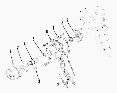
To remove pump, drain cooling system and remove radiator, if necessary,
for access to pump. Remove fan belt, then unbolt and remove water pump.
To disassemble pump, remove fan pulley using a suitable puller. Unseat
pump shaft bearing front retaining ring, then press shaft and bearings
forward out of impeller and pump body. Remove seal assembly from pump
body. All water pump parts are available individually. To reassemble
pump, reverse the disassembly procedure. On pumps equipped with fan
pulley retaining nut, tighten nut to a torque of 70-78 Nm (50-58
ft.-lbs.).
Fan shaft
To remove cooling fan and shaft assembly, drain cooling system and
remove radiator. Remove fan belt and fan. Remove retaining nut and
withdraw fan shaft, pulley and bearings. Renew parts as needed.
Reinstall fan shaft assembly by reversing removal procedure.
Kubota L2350, L245DT, L2550, L235 - Engine
Components
Cylinder head
To remove cylinder head, first drain cooling system and disconnect
battery cables. Remove hood, muffler and side covers (if equipped).
Remove upper radiator hose, coolant return hose and intake manifold
hose. Disconnect decompressor control cable. Remove injection lines and
nozzle assemblies and cap all exposed fittings to prevent entry of dirt.
Remove alternator adjusting bracket. Remove valve lever cover. Remove
valve levers and shaft assembly and withdraw push rods. Remove cap
screws and nuts securing cylinder head and lift head off cylinder block.
One or more shims may he installed between gasket and cylinder head to
adjust clearance between cylinder head and piston tops. Identify shims
when cylinder head is removed, then install an equal number of shims
when head is reinstalled. To check piston to head clearance, insert a
soft lead wire through injection nozzle holder hole. Rotate crankshaft
by hand until lead wire is flattened by piston top. Measure thickness of
flattened wire to determine top clearance which should be 0.7-0.9 mm
(0.028-0.035 inch).
Because of minimum amount of clearance that exists between valves and
piston tops, loosen valve lever adjusting screws before reinstalling
valve levers and shaft assembly to prevent possible damage to valves.
Check cylinder head surface for distortion using a straightedge and
feeler gage. If a 0.05 mm (0.002 inch) feeler gage can be inserted
between cylinder head and straightedge, head surface should be refaced
with a surface grinder. A maximum of 0.5 mm (0.020 inch) of material may
be removed to true cylinder head surface. When installing cylinder head,
use new head gasket and install shims (if used) between gasket and
cylinder head. Be sure sealing surfaces are clean and dry. Apply light
coat of engine oil to threads of retaining nuts and cap screws.
Tightening torque is 73.5-78.4 Nm (55-58 ft.-lbs.). Adjust valve
clearance and compression release mechanism. Retorque cylinder head cap
screws and nuts after running engine for approximately 30 minutes using
proper tightening sequence.
Compression release
Compression release mechanism is contained within valve lever cover.
When decompressor knob is pulled, decompressor shaft rotates allowing
adjusting screws to contact exhaust valve levers. The decompressor
screws will hold exhaust valves slightly open, reducing compression
resistance when starting engine, until decompressor knob is returned to
normal operating position. To adjust compression release, remove
adjusting covers from valve lever cover. Pull decompressor knob out,
then turn crankshaft by hand until exhaust valve being adjusted is
completely closed (piston at TDC compression stroke). Turn decompressor
screw down until it contacts valve lever, then turn screw down an
additional 1 to 1,5 turns to obtain specified valve opening of
0.750-1.125 mm (0.030-0.044 inch). Tighten locknut while holding
adjusting screw. Repeat adjustment procedure for remainder of exhaust
valves. After adjustment is completed, pull knob out and turn crankshaft
by hand to make certain valves do not contact piston tops.
Kubota L2350, L245DT, L2550, L235 - Valves and
Seat
Intake and exhaust valves are not interchangeable. All valves seat
directly in cylinder head. Valve face and seat angles are 45 degrees for
all valves. Recommended valve seat width is 2.1 mm (0.080 inch). Valve
stem diameter is 7.960-7.975 mm (0.3134-0.3140 inches) for all valves.
Face of valves should be recessed 1.1-1.3 mm (0.043-0.051 inch) below
surface of cylinder head. Maximum allowable recession is 1.6 mm (0.063
inch). Whenever valves are renewed or reseated, be sure to adjust
compression release mechanism as previously outlined. Valve clearance,
gap between valve stem end and valve lever, is adjusted with engine
cold. Recommended gap is 0.18-0.22 mm (0.007-0.009 inch) for both intake
and exhaust. Due to close clearance between valves a pistons, severe
damage can result from inserting feeler gage between valve stem and
valve lever with engine running. Do not attempt to adjust valve
clearance with engine running. To adjust valve clearance, proceed as
follows: Loosen valve lever adjusting screw locknuts. Rotate crankshaft
by hand to position number one piston at top dead center of compression
stroke. Using a feeler gage to measure clearance, adjust valves for
number one cylinder. Adjust remaining valves in sequence of firing order
after positioning each piston at top dead center of compression stroke.
Valve Guides
Intake and exhaust valve guides are semi-finished and must be reamed
after installation in cylinder head. Intake and exhaust valve guides are
not interchangeable as exhaust guide is equipped with a carbon scraper
at lower end of guide. Press new guides into cylinder head until guide
shoulder is seated against surface of head. Kubota D1102, D1402 diesel
engines are equipped with cup type stem seals which fit over stem end of
valve guide. Desired operating clearance of valve stem in guide is
0.04-0.07 mm (0.0016-0.0028 inch). Maximum allowable clearance is 0.10
mm (0.0039 inch). Recommended finished inside diameter of valve guides
is 8.015-8.030 mm (0.3156-0.3161 inch).
Valve springs and Valve levers
Valve springs are interchangeable for intake and exhaust valves.
Approximate free length is 42 mm (1.65 inches) and minimum allowable
free length is 41.2 mm (1.62 inches) on all models. Renew springs which
are distorted, heat discolored or fail to meet following test
specifications: Springs should test 117.7 N (26.5 pounds) when
compressed to a length of 35.15 mm (1.384 inches). Minimum test
specifications are 100 N (22.5 pounds) at 35.15 mm (1.384 inches).
Intake and exhaust valve levers (rocker arms) are interchangeable on all
models. However, it is recommended that valve levers be reinstalled in
their original positions if not being renewed. All valve levers are
equipped with renewable bushings. When installing new bushing, be sure
hole in bushing is aligned with corresponding hole in valve lever.
Recommended operating clearance of shaft in valve levers is 0.02-0.07 mm
(0.0008-0.0028 inch) and allowable limit is 0.15 mm (0.006 inch). Shaft
diameter should be 13.973-13.984 mm (0.5501-0.5506 inch) and bushing
inside diameter should be 14.002-14.043 mm (0.5513-0.5529 inch). Valve
levers and shaft are lubricated by oil metered to shaft support bracket
from rear camshaft bearing. When assembling valve lever assembly, make
sure all oil passages are open and properly positioned.
Cam followers and valve timing
Kubota D1102, D1402 engines are equipped with barrel type cam followers
(tappets) which can be removed from the top after removing cylinder
head. Cam followers operate directly in unbushed crankcase bores on all
models. Check for wear or other damage and renew if necessary. Check
camshaft at same time and renew if cam lobe surface is chipped, scored
or excessively worn. Valve timing - Valve timing is correct when timing
marks on timing gear train are aligned. Timing gear cover must he
removed to check timing marks.
Timing gear cover
To remove timing gear cover, first separate front axle assembly from
engine as follows: Drain cooling system. Remove hood, muffler, side
covers and side rails (if equipped). Disconnect battery cables and
remove battery. Disconnect upper and lower radiator hoses and intake
manifold hose. Disconnect steering drag link from front axle. On
tractors equipped with booster-type power steering, disconnect booster
cylinder from front support. On tractors with front-wheel drive, remove
drive shaft. On all models, support tractor underneath clutch housing
and front axle. Remove fasteners securing front axle support to engine
block, then roll front axle assembly and radiator as a unit away from
engine. Remove injection pump side cover, then disconnect governor
spring from governor lever. Remove speed control plate, then disconnect
start spring from gear cover. Remove fan belt, then use a suitable
puller to remove crankshaft pulley. Remove alternator and mounting
bracket. Remove hour meter drive (if equipped) from front cover.
Disconnect water pump by-pass hose. Remove retaining cap screws and
withdraw timing gear cover. Crankshaft front oil seal can be renewed at
this time. Seal should be installed with lip to the rear and front edge
flush with front of cover bore. Apply grease to oil seal lip prior to
reinstalling front cover. When reinstalling timing gear cover, be sure
all O-rings are in position and water inlet nipple in cylinder block is
free of rust, burrs or other imperfections which might damage O-ring. Be
sure hour meter drive tang engages slot in end of fuel camshaft.
Complete reassembly by reversing disassembly procedure.
Timing gear
Normal backlash between any two gears in timing train is 0.042-0.115 mm
(0.0017-0.0045 inch) with a maximum allowable limit of 0.3 mm (0.012
inch). Crankshaft gear is light press fit on shaft and can be removed
using a suitable puller. On Kubota L2550, a separate oil pump drive
gear, installed in front of crankshaft gear, is also a light press fit.
To install new gear, heat first to a temperature of 80-95C (175-200F)
and install immediately. Make sure timing mark faces forward. Camshaft
gear is a light press fit on shaft. Gear and shaft should be removed
from cylinder block as a unit, then press shaft out of gear. Injection
pump gear is a light press fit on fuel camshaft and is retained by a
snap ring. Idler gear is equipped with renewable bushings. When
reassembling timing gears, align timing marks.
Kubota L2350, L245DT, L2550, L235 Engine -
Camshaft
To remove camshaft, first remove timing gear cover. Remove cylinder head
and lift out cam followers. Remove two cap screws retaining camshaft
thrust plate, then withdraw camshaft and drive gear as a unit. Be
careful not to damage camshaft or bearing bores. Gear can be removed
using a suitable press. Thrust plate controls camshaft or bearing bores.
Gear can be removed using a suitable press. Thrust plate controls
camshaft end play. Camshaft bearing journal diameter should be
39.934-39.950 mm (1.5722-1.5728 inches). Camshaft operates in unbushed
bores in cylinder block. Bearing bore inside diameter should be
40.000-40.025 mm (1.5748-1.5758 inches). Desired operating clearance is
0.050-0.091 mm (0.0020-0.0036 inch) with a maximum limit of 0.15 mm
(0.006 inch). Measured cam height should be 33.36 mm (1.313 inches) and
minimum allowable height is 33.31 mm (1.311 inches). When reinstalling
camshaft, thoroughly lubricate cams and bearing journals.
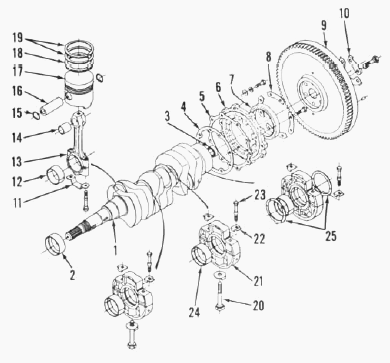
Rod and piston units
Connecting rod and piston units may be removed from above after removing
cylinder head and oil pan. Be sure to remove ring ridge (if present)
from top of cylinder before attempting to push piston out. Be sure to
identify piston, rod and cylinder from which they came so units can be
reassembled in original positions. Before removing piston from rod, mark
top of piston in relation to alignment marks on connecting rod and
identify piston and connecting rod as a pair to ensure correct assembly.
When reinstalling piston and rod units, be sure connecting rod match
marks are aligned and facing toward injection pump side of engine. Apply
engine oil to connecting rod cap screws and tighten to a torque of 37-41
Nm (27-30 ft.-lbs.).
Pistons and rings
Three-ring, cam ground aluminum pistons are used on all models. Pistons
and rings are available in standard size and 0.5 mm (0.020 inch)
oversize. Piston ring end gap should be 0.30-0.45 mm (0.012-0.018 inch)
for compression rings and 0.25-0.40 mm (0.010-0.016 inch) for oil
control ring. Maximum allowable end gap for any ring is 1.25 mm (0.049
inch). Top compression ring is half-keystone type and side clearance is
not measured. Second compression ring should have a side clearance of
0.09-0.12 mm (0.004-0.005 inch). Oil control ring side clearance should
be 0.02-0.05 mm (0.001-0.002 inch). When installing rings onto piston,
be sure manufacturer's name or TOP mark on ring is towards top of
piston. Make certain notched outer edge on second compression ring is
facing down. Position coil expander joint on opposite side of oil
control ring gap. Stagger rings on piston so end gaps are 90 degrees
apart with no gap aligned with piston pin. Piston pin - The full
floating piston pin is a transition fit in piston bosses at room
temperature. Heat piston prior to reassembly to ease piston pin
installation. Piston pins are available in standard size only. Inside
diameter of pin bore in piston should be 23.000-23.013 mm (0.9055-0.9060
inch) and maximum usable bore diameter is 23.053 mm (0.9076 inch).
Piston pin diameter should be 23.002-23.011 mm (0.9056-0.9059 inch). Pin
should have an operating clearance of 0.014-0.038 mm (0.0006-0.0015
inch) in connecting rod bushing. Maximum allowable clearance is 0.15 mm
(0.006 inch).
Cylinder sleeves
Cylinder sleeves used in Kubota D1102, D1402 engines are dry-type
sleeves which are a tight press fit in cylinder block. Sleeves which are
worn beyond the allowable limit of 0.15 mm (0.006 inch) may be bored and
honed to accept 0.5 mm (0.020 inch) oversize pistons and rings. When
oversized sleeve is worn beyond allowable limit, sleeve must be renewed.
New sleeve should be pressed into block bore until flush with top of
block. New sleeves are semi-finished and must be bored and honed to
obtain desired clearance of 0.075-0.100 mm (0.003-0.004 inch) for piston
skirt. Standard finished diameter of sleeve is as follows: On Kubota
L235, L245DT, L2350, diameter is 76.00-76.02 mm (2.992-2.993 inches). On
Kubota L2550, diameter is 82.00-82.02 mm (3.228-3.229 inches).
Connecting rods and bearings
Connecting rod bearings are slipping, precision type, renewable from
below after removing oil pan and connecting rod cap. When installing
connecting rods, make certain match marks on cap and rod are aligned and
face AWAY from camshaft side of engine. Connecting rod bolt torque is
37-41 Nm (27-30 ft.-lbs.) with threads oiled. Standard crankpin diameter
is 43.959-43.975 mm (1.7307-1.7313 inches) for all models. Desired
operating clearance between crankpins and bearings is 0.035-0.093 mm
(0.0014-0.0037 inch) and maximum allowable clearance is 0.20 mm (0.008
inch). Connecting rod bearings are available in standard size and also
0.20 mm (0.008 inch) and 0.40 mm (0.016 inch) undersize.
Kubota L2350, L245DT, L2550, L235 - Crankshaft
and main bearings
On Kubota D1102, D1402 diesel engines crankshaft and main bearing
assemblies are removed from rear of engine as follows: Remove engine
assembly, then remove rod and piston units, timing gear cover,
crankshaft gear, flywheel and rear bearing cover. Remove bearing case
retaining cap screws, then bump crankshaft and bearings rearward out of
cylinder block. Note that bearing cases are minimum clearance in
cylinder block bores to provide oil pressure transfer through drillings
in bearing cases. Front main bearing is a one-piece bushing type,
pressed into front face of cylinder block. Remainder of main bearings
are two-piece bushing type contained in two-piece bearing cases.
Crankshaft end play is controlled by thrust washers located on rear main
bearing. Standard main journal diameter is 51.921-51.940 mm (2.044-2.045
inches). Desired diametral clearance in front main bearing is
0.040-0.118 mm (0.0016-0.0046 inch) and in remainder of bearings is
0.040-0.104 mm (0.0016-0.0041 inch). Maximum allowable clearance for all
main bearings is 0.20 mm (0.008 inch). Bearings are available in
standard size as well as 0.20 mm (0.008 inch) and 0.40 mm (0.016 inch)
undersize.
Crankshaft end play should be 0.15-0.30 mm (0.006-0.0012 inch) with and
allowable limit of 0.5 mm (0.020 inch). Thrust washers are available in
standard size and also 0.20 mm (0.008 inch) and 0.40 mm (0.016 inch)
oversize’s. When reinstalling thrust washers, be sure oil grooves are
facing outward. Reinstall crankshaft by reversing the removal procedure
while noting following items: Assemble bearing cases starting with
smallest outside diameter case at front of crankshaft. Be sure to align
bearing case match marks. Tighten bearing case cap screws to a torque of
30-34 Nm (22-25 ft.-lbs.) and case locating cap screws to 64-68 Nm
(47-50 ft.-lbs.). Lubricate lip of rear oil seal before reinstalling
rear cover over crankshaft hub. Tighten flywheel retaining cap screws to
a torque of 98-108 Nm (73-80 ft.-lbs.). Crankshaft rear oil seal - The
lip type crankshaft rear oil seal is contained in rear bearing cover and
can be renewed after splitting tractor between engine and clutch housing
and removing clutch and flywheel. Install new seal with lip towards
inside and coat seal lip with grease prior to reassembly.
Flywheel
Flywheel is retained to crankshaft flange by six evenly spaced cap
screws and can be installed in any of six positions. To be sure flywheel
will be reinstalled correctly, remove one of the retaining cap screws
and spray flywheel and exposed cap screw hole with quick drying paint.
Then, when reinstalling flywheel, make certain paint marks are in
register. Flywheel ring gear is a shrink fit on flywheel. Heat gear
evenly prior to installation, then install with beveled end of teeth
towards front of flywheel. Inspect pilot bearing and renew if necessary.
Make sure mating surfaces of flywheel and crankshaft flange are clean
and free of dirt, rust or burrs. Tighten retaining cap screws evenly to
a torque of 98-108 Nm (73-80 ft.-lbs.).
Oil pump
The rotary type engine oil pump mounts on front of cylinder block and is
driven by crankshaft gear. Pump can be removed after removing timing
gear cover. To check engine oil pressure, remove oil pressure switch and
install a pressure gage. With engine at operating temperature, check oil
pressure at idle speed and rated speed. Pressure should be at least 100
kPa (14 psi) at idle speed and should be within range of 295-440 kPa
(43-60 psi) at rated engine speed. Oil pump inner rotor to outer rotor
operating clearance should be 0.10-0.16 mm (0.004-0.006 inch) and
maximum allowable clearance is 0.20 mm (0.008 inch). Clearance between
body and outer rotor should be 0.11-0.19 mm (0.004-0.007 inch) and a
maximum allowable clearance of 0.25 mm (0.010 inch). End clearance
between rotors and cover should not exceed 0.2 mm (0.008 inch). Oil pump
is available only as an assembled unit. Renew complete pump if it fails
to meet specifications.
________________________________________________________________________________
________________________________________________________________________________________
 SPECIFICATIONS
 LOADERS
 ENGINES
 INSTRUCTIONS
 PROBLEMS
________________________________________________________________________________________
 B2320
B2320 B2630
B2630 B2920
B2920 B3300SU
 BX2360
________________________________________________________________________________________
 L245
L245 L260
L260 L275
L275 L285
L285 L305
L305________________________________________________________________________________________
________________________________________________________________________________________
 D662
D662 D722
D722 D750
D750 D782
D782 D850
D850________________________________________________________________________________________
 LA302
LA302 LA304
LA304 LA340
LA340 LA344
LA344 LA351
LA351________________________________________________________________________________________
 BX2660
 L2501
L2501 L3240
L3240 L3540
L3540 L3940
L3940________________________________________________________________________________________
 D902
D902 D905
D905 D950
D950 D1005
D1005 D1100
D1100________________________________________________________________________________________
________________________________________________________________________________________
 B1630
B1630 BF400
BF400 BF400G
 LA181
LA181 LA203
LA203________________________________________________________________________________________
 LA211
LA211 LA243
LA243 LA271
LA271 LA272
LA272 LA301
LA301________________________________________________________________________________________
 L175
L175 L185
L185 L210
L210 L225
L225 L235
L235________________________________________________________________________________________
 D1105
D1105 D1503
D1503 D1703
D1703 D1803
D1803 V1200
V1200________________________________________________________________________________________
 L4400
L4400 L4600
L4600 L5040
L5040 L5740
L5740 MX4700
________________________________________________________________________________________
 LA352
LA352 LA364
LA364 LA401
LA401 LA402
LA402 LA403
LA403________________________________________________________________________________________
 LA434
LA434 LA463
LA463 LA481
LA481 LA482
LA482 LA504
LA504________________________________________________________________________________________
 V1205
V1205 V1305
V1305 V1505
V1505 V2203
V2203 V2403
V2403________________________________________________________________________________________
 B2710
B2710 BX23S
BX23S B3350
B3350 BX1880
 L4701
L4701________________________________________________________________________________________
 LA513
LA513 LA514
LA514 LA524
LA524 LA525
LA525 LA534
LA534________________________________________________________________________________________
 LA555
LA555 LA680
LA680 LA681
LA681 LA682
LA682 LA703
LA703________________________________________________________________________________________
 Z482
Z482 Z602
Z602 Z750
Z750 Z1100
Z1100 Z1300
Z1300________________________________________________________________________________________
 M100GX
 M135GX
 M6040
M6040 M8540
M8540 M95X
M95X________________________________________________________________________________________
 LA714
LA714 LA723
LA723 LA724
LA724 LA764
LA764 LA765
LA765________________________________________________________________________________________
 LA805
LA805 LA844
LA844 LA852
LA852 LA853
LA853 LA854
LA854________________________________________________________________________________________
 M5-091
 BX2680
 MX5200
 BX2380
 L3901
L3901________________________________________________________________________________________
 LA1002
 LA1055
 LA1065
 LA1153
 LA1154
________________________________________________________________________________________
 LA1251
 LA1301S
 LA1353
 LA1403
 LA1601S
________________________________________________________________________________________
 LA1854
 LA1944
 LA1953
 LA2253
 LM2605