________________________________________________________________________________
Massey Ferguson 6475 Tractor Specs Overview

Massey Ferguson 6475 Tractor Engine
Engine Model - Perkins 1106D-E66TA
Engine Power, Rated, hp (kW) - 135 (101)
Engine Speed, rpm - 2200
Power Boost, hp (kW) - No boost
Fuel Tank, gal (L) - 70 (270)
Cylinders - 6
Displacement, cu in (L) - 403 (6.6)
Engine Bore, in (mm) - 4.134 (105)
Engine Stroke, in (mm) - 5.0 (127)
Block Design, Replaceable Liners - Parent bore
Aspiration, Turbocharged or Naturally Aspirated - Turbo air to air
aftercooled
Fuel System Type - High Pressure Common Rail
Fuel System Control - Electronic
Fuel Injection to combustion chamber - Direct
Emission Level - Tier 3
Exhaust Pipe - Vertical
Fan Drive Type - Belt
System Rating, Volts - 12
Alternator Rating, Amps - 120 Std / 150 Opt
MF 6475 Tractor Transmission
Description - Auto 6 Semi Powershift
Transmission Type - Synchronized Gear
Forward / Reverse Speeds - 24F / 24R
Maximum Speed Forward, mph (kph) - 24.9 (40)
Creeper Range - Yes
Shuttle (Forward-Reverse) - Yes
Massey Ferguson 6475 Tractor PTO
PTO Horsepower, hp (kW) - 110 (82)
PTO Speeds, rpm - 540 / 540E / 1000 / 1000E
PTO Type - Independent
Wheels
Drive Wheels - 2WD / 4WD
Steering - Front Steer
Rear Axle
Final Drive - Planetary / Inboard
Axle Output End - Flange standard / Bar Optional
Suspended Front Axle Available - Opt / Std w/50Kph Trans
Brakes
Brake Type - Wet Disc
MF 6475 Tractor Hydraulic
System
Hydraulic System Type - Closed Center PFC
Main Hydraulic Pump Type - Gear Pump
Standard Pump Flow, gpm (Lpm) - 29 (110)
Standard Remote Valves - 2
3-Point Hitch Features
3-Point Hitch - Category 2
Draft Sensing or Lift Control - Lower Link
Draft Link Ends Adjustable - Yes
3-Point Hitch Lift Capacity
Standard Lift Capacity 24 Inches behind pin, lb (kg) - 9,391 (4260)
MF6475 Tractor Drawbar
Drawbar Description - Swinging
Wheelbase
2WD, in (mm) - 111.3 (2827)
4WD, in (mm) - 111.3 (2827)
Tire Size
Front Tire Size, 2WD - 10.00 x 16
Front Tire Size Width, 4WD - 14.9R28
Rear Tire Size Width - 18.4R38
Massey Ferguson 6475 Tractor GPA20
rear axle - Auto-hitch
MF 6475 Tractor hitches can be attached to
different types of hitches or hooks:
- Swinging drawbar (different types)
- Clevis on adjustable scale (different types)
- Stud for semi-mounted trailer
- Pick-up hitch
Some equipment can be fitted simultaneously depending on technical
possibilities, options and countries.
Adjusting the Massey Ferguson 6475
Tractor auto-hitch tie-rods and the control
Adjusting the tie rods
On the support, disconnect the lower clevises of the tie-rods and the
control cable. Start the engine. Assisted by an operator, activate the
internal or external linkage control (if fitted) so that the linkage
arms are in the maximum raised position (continuous pumping).
Compress the lower part of the hitch along the MF6475
Tractor centreline, as using a trolley jack to obtain a dimension X of 6
to 14 mm between the top of the main support and the top of the mobile
plate.
Adjust the length of the tie rods by turning their square section
sliders in order to engage the clevises in the pins of the support.
Install the pins. Remove the jack. Reconnect the control. Check the
operation of the mobile plate and the hitch locking mechanism using the
lever.
Adjusting the control
On the lever
Place the lever in the "rest" position.
Adjust the nuts to obtain the same thread length on each side of the
support. Check that the cable is not pinched.
On the auto-hitch
Screw the clevis level with the threaded end of the cable.
Install the clevis onto rod using the clip while ensuring that the rod
is in the locked position. Tighten the nut.
Install the sheath end in the support and tighten the nuts and so that
there is no play in the cable and the cable is not pinched.
During adjustment, ensure that rod remains locked.
Operating principle of the Dromone
retractable hitch
Construction
The MF 6475 Tractor auto-hitch assembly comprises a main support
attached to the centre housing and a mobile plate that can be raised or
lowered via the adjustable tie-rods of the linkage system.
Plate lowered
When the system is released by the lever in the cab, the mobile plate
can be lowered to the ground by the linkage system. Once the tractor is
in position, the trailer drawbar can be hitched on.
Plate raised
In this configuration, the locking safety on the retractable hitch is
activated at maximum retraction, with the plate previously raised and
engaged. The principle involves two mechanical locks located at the rear
of the main support.
When the above conditions are obtained, the locks enter their respective
recesses in the retractable hitch and prevent any inadvertent movement.
________________________________________________________________________________
 SPECS
 LOADERS
 MAINTENANCE
 PROBLEMS
________________________________________________________________________________________
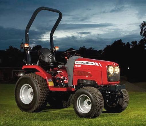 MF 1523
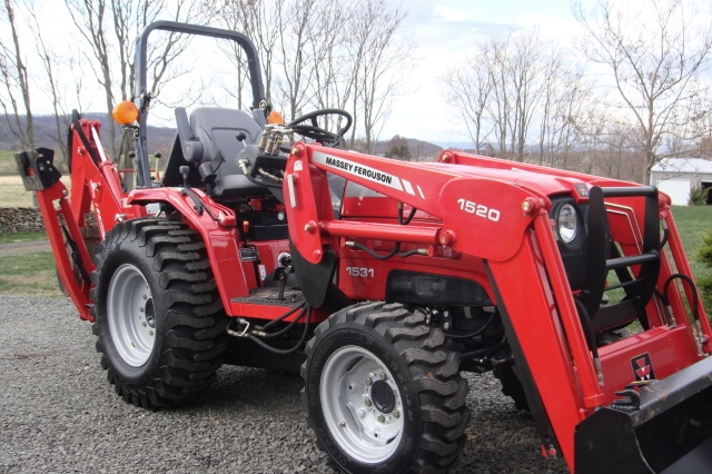 MF 1531
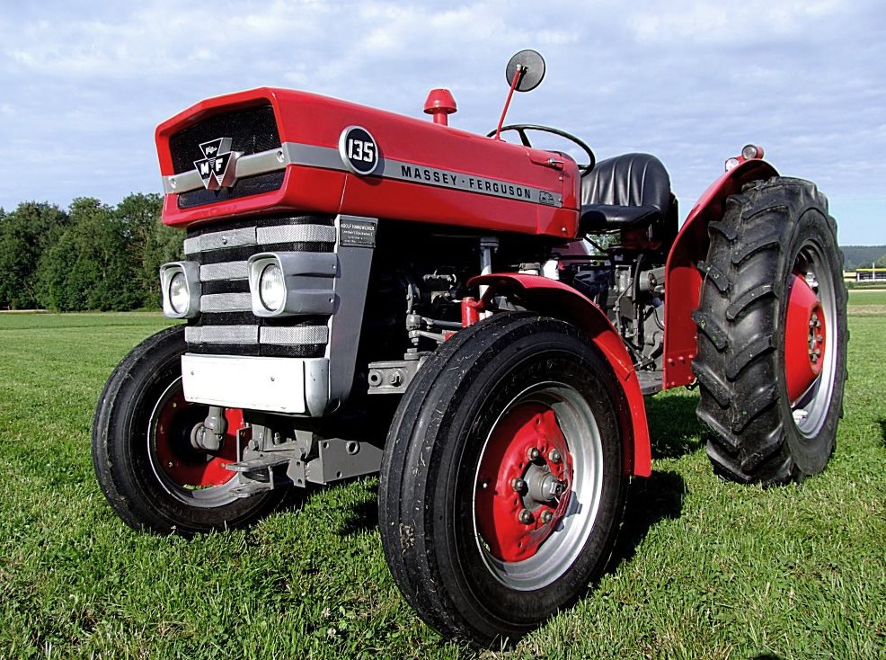 MF 135
 MF 1547
 MF 1635
________________________________________________________________________________________
 231
 231S
 235
 240
 241
________________________________________________________________________________________
_______________________________________________________________________________________
 255
 265
 274
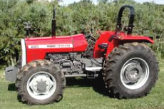 285
 375
________________________________________________________________________________________
________________________________________________________________________________________
 916X Loader
 921X Loader
 926X Loader
 931X Loader
 936X Loader
________________________________________________________________________________________
 941X Loader
 946X Loader
 951X Loader
 956X Loader
 988 Loader
________________________________________________________________________________________
 1655
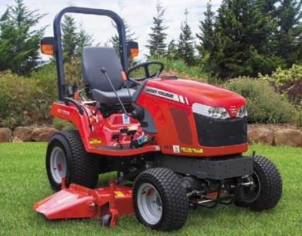 GS1705
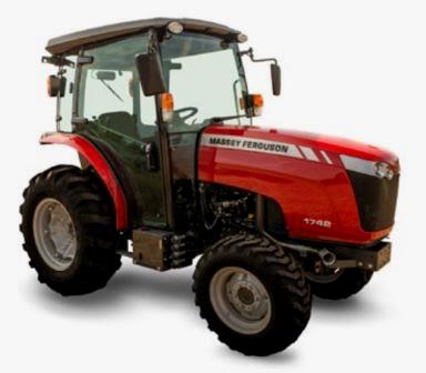 1742
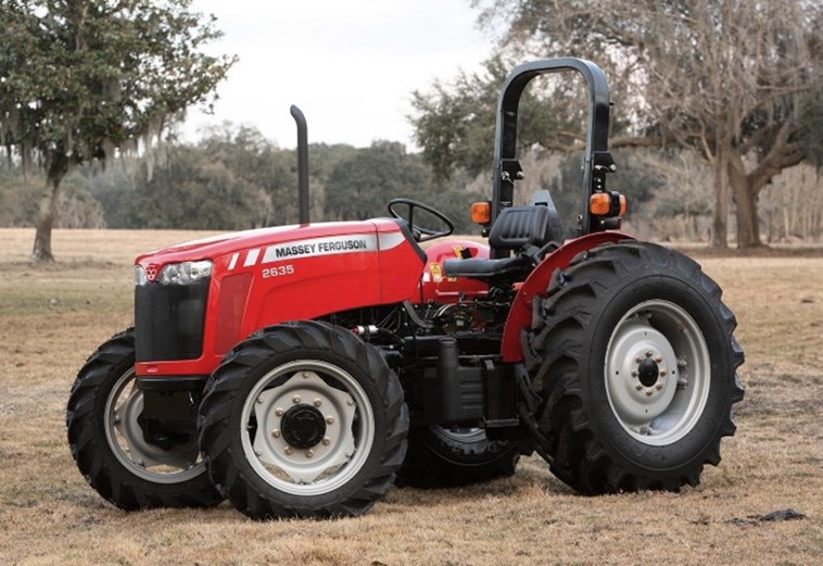 2635
 4608
________________________________________________________________________________________
 1080
 1100
 2615
 3050
 3060
________________________________________________________________________________________
 4708
 5455
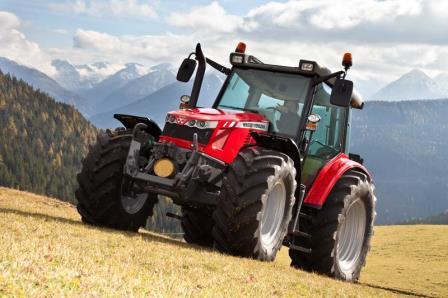 5450
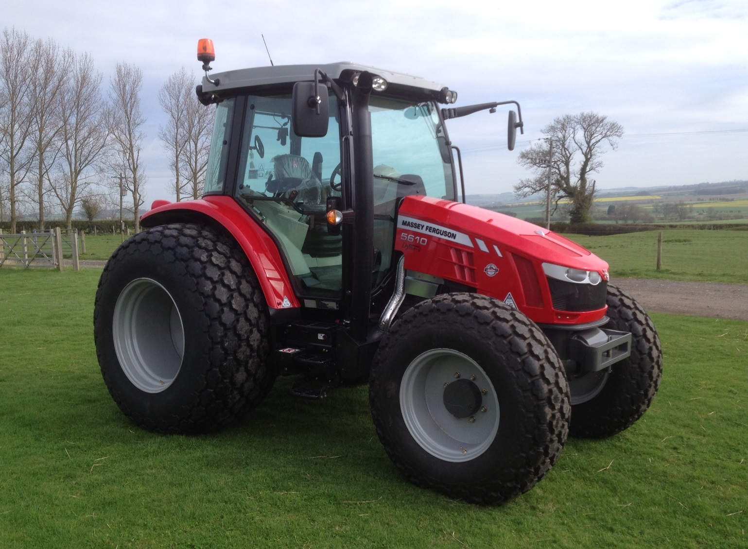 5610
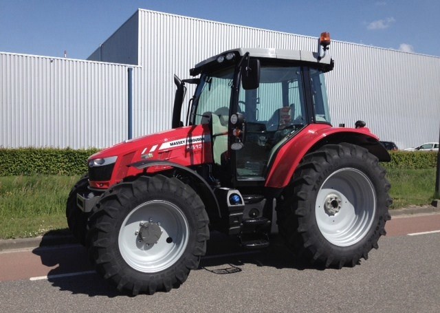 5613
________________________________________________________________________________________
 DL95 Loader
 DL100 Loader
 DL120 Loader
 DL125 Loader
 DL130 Loader
________________________________________________________________________________________
 DL135 Loader
 DL250 Loader
 DL260 Loader
 L90 Loader
 L100 Loader
________________________________________________________________________________________
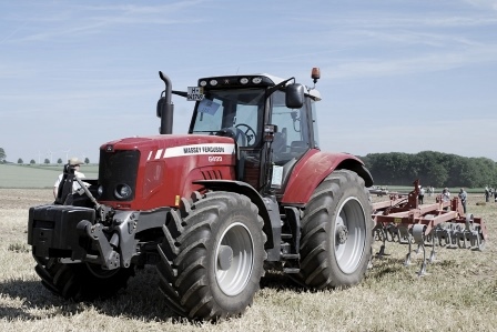 6499
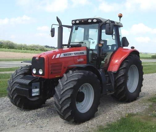 7480
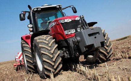 7618
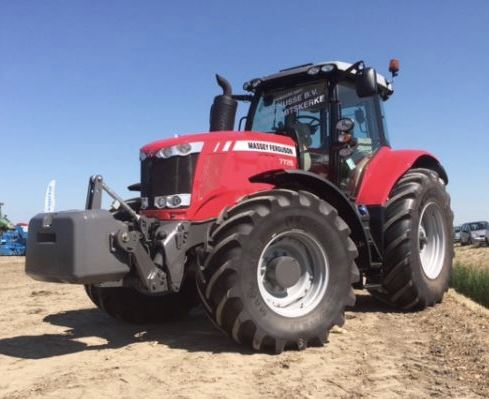 7726
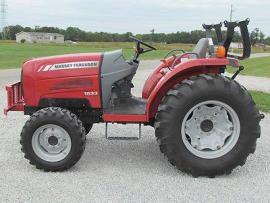 1533
________________________________________________________________________________________
 2604H
 2607H
 4455
 4610M
 4710
________________________________________________________________________________________
 L105E Loader
 L210 Loader
 1014 Loader
 1016 Loader
 1462 Loader
________________________________________________________________________________________
 1525 Loader
 1530 Loader
 232 Loader
 838 Loader
 848 Loader
________________________________________________________________________________________
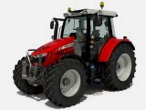 5712SL
 6713
 6715S
 7475
 7615
________________________________________________________________________________________
 7716
 7724
 8240
 8650
 8732
________________________________________________________________________________________
 246 Loader
 1036 Loader
 1038 Loader
 1080 Loader
 856 Loader