
________________________________________________________________________________
Massey Ferguson 6490 Tractor Specs Review
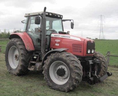
Massey Ferguson 6490 Tractor Engine
Engine Model - Agco Sisu Power 66 CTA
Engine Power, Rated, hp (kW) - 170 (127)
Engine Speed, rpm - 2200
Power Boost, hp (kW) - No boost
Fuel Tank, gal (L) - 93.8 (355)
Cylinders - 6
Displacement, cu in (L) - 403 (6.6)
Engine Bore, in (mm) - 4.25 (108)
Engine Stroke, in (mm) - 4.73 (120)
Block Design, Replaceable Liners - Replaceable wet liners
Aspiration, Turbocharged or Naturally Aspirated - Turbo air to air
aftercooled
Fuel System Type - High Pressure Common Rail
Fuel System Control - Electronic
Fuel Injection to combustion chamber - Direct
Emission Level - Tier 3
Exhaust Gas Recirculation - Internal EGR
Exhaust Pipe - Vertical
Fan Drive Type - Belt
System Rating, Volts - 12
Alternator Rating, Amps - 120 Std / 150 Opt
MF 6490 Tractor Transmission
Description - Auto 6 Semi Powershift
Transmission Type - Synchronized Gear
Forward / Reverse Speeds - 24F / 24R
Maximum Speed Forward, mph (kph) - 24.9 (40)
Creeper Range - Yes
Shuttle (Forward-Reverse) - Yes
Massey Ferguson 6490 Tractor PTO
PTO Horsepower, hp (kW) - 140 (104.4)
PTO Speeds, rpm - 540 / 540E / 1000 / 1000E
PTO Type - Independent
Wheels
Drive Wheels - 2WD / 4WD
Steering - Front Steer
MF6490 Tractor Rear Axle
Final Drive - Planetary / Inboard
Axle Output End - Bar standard
Axle Bar Diameter, in (mm) - 3.74 (95)
Suspended Front Axle Available - Opt / Std w/50Kph Trans
Brakes
Brake Type - Wet Disc
Massey Ferguson 6490 Tractor Hydraulic
System
Hydraulic System Type - Closed Center PFC
Main Hydraulic Pump Type - Gear Pump
Standard Pump Flow, gpm (Lpm) - 29 (110)
Optional Pump Flow, gpm (Lpm) - 39 (150)
Number of Standard Remote Valves - 3
3-Point Hitch Features
3-Point Hitch - Category 3
Optional Hitch - Category 3N
Draft Sensing or Lift Control - Lower Link
Draft Link Ends Adjustable - Yes
3-Point Hitch Lift Capacity
Standard Lift Capacity 24 Inches behind pin, lb (kg) - 16,500 (7480)
MF 6490 Tractor Drawbar
Drawbar Description - Swinging
Wheelbase
2WD, in (mm) - 118 (2996)
4WD, in (mm) - 118 (2996)
Tire Size
Front Tire Size, 2WD - 11.00 x 16
Front Tire Size Width, 4WD - 14.9R30
Rear Tire Size Width - 18.4R42
MF 6490 Tractor GPA40
rear PTO Clutch
Rear PTO clutch engagement and disengagement are controlled electrically
by a proportional solenoid valve, which is itself controlled by the MF6490 Tractors electronic system.
The clutch, located at the front and in the upper section of the centre housing, controls the operation of the rear PTO.
It is connected in rotation to the engine flywheel via a vibration
damper fixed to the flywheel and a line comprising two shafts.
It consists of a unit supported by two ball bearings centred in a
support fitted to the centre housing. The sleeve supports the ball
bearing, the drive hub and the piston.
The clutch housing comprises:
- at the front, a helical gear, fixed using screws, which transmits the
movement to the hydraulic pumps. For Massey Ferguson 6490 Tractor
equipped with GTA1540 transmission, gear P1 has spur cut teeth. It is
also fixed using screws;
- at the rear, a bell housing with a set of discs and intermediate
plate. A sealing ring minimises leakage between the rear end of the
gearbox upper shaft and the clutch unit.
Clutch engaged position
The MF 6490 Tractor rear PTO clutch is supplied via the 17 bar (GTA1040
tractor transmission) or 21 bar (tractors equipped with GTA1540
transmission) low pressure hydraulic system and via a proportional
solenoid valve fitted to the right-hand hydraulic cover plate.
A transfer pipe hydraulically links the right-hand hydraulic cover plate
and the clutch support.
Pressurised oil enters the unit through hole and then flows to the rear
of the piston via an internal channel. It pushes the piston, which
compresses the discs and the intermediate plates.
The intermediate plates are attached to the bell housing by lugs. The discs are splined to the hub. The movement is then transmitted to the rear PTO driving gears via a shaft.
When the clutch is engaged, the PTO brake piston located in the rear
housing is at rest and releases the lower PTO shaftline.
Clutch disengaged position
If the solenoid valve is no longer supplying the rear PTO clutch, the
piston is returned against the unit by the spring.
The oil in the piston chamber is directed to the return by the solenoid
valve. The valve ball leaves its seat, thus assisting the decompression
of the chamber.
________________________________________________________________________________
________________________________________________________________________________________
 SPECS
SPECS LOADERS
 MAINTENANCE
 PROBLEMS
________________________________________________________________________________________
 MF 1523
 MF 1531
 MF 135
 MF 1547
 MF 1635
________________________________________________________________________________________
________________________________________________________________________________________
 231
231 231S
231S 235
235 240
240 241
241________________________________________________________________________________________
 255
255 265
265 274
274 285
285 375
375________________________________________________________________________________________
________________________________________________________________________________________
 916X Loader
 921X Loader
 926X Loader
 931X Loader
 936X Loader
________________________________________________________________________________________
 941X Loader
 946X Loader
 951X Loader
 956X Loader
 988 Loader
________________________________________________________________________________________
 1655
1655 GS1705
 1742
1742 2635
2635 4608
4608________________________________________________________________________________________
 1080
1080 1100
1100 2615
2615 3050
3050 3060
3060________________________________________________________________________________________
 4708
4708 5455
5455 5450
5450 5610
5610 5613
5613________________________________________________________________________________________
 DL95 Loader
 DL100 Loader
 DL120 Loader
 DL125 Loader
 DL130 Loader
________________________________________________________________________________________
 DL135 Loader
 DL250 Loader
 DL260 Loader
 L90 Loader
 L100 Loader
________________________________________________________________________________________
 6499
6499 7480
7480 7618
7618 7726
7726 1533
1533________________________________________________________________________________________
 2604H
2604H 2607H
2607H 4455
4455 4610M
4610M 4710
4710________________________________________________________________________________________
 L105E Loader
 L210 Loader
 1014 Loader
 1016 Loader
 1462 Loader
________________________________________________________________________________________
 1525 Loader
 1530 Loader
 232 Loader
 838 Loader
 848 Loader
________________________________________________________________________________________
 5712SL
 6713
6713 6715S
6715S 7475
7475 7615
7615________________________________________________________________________________________
 7716
7716 7724
7724 8240
8240 8650
8650 8732
8732________________________________________________________________________________________
 246 Loader
 1036 Loader
 1038 Loader
 1080 Loader
 856 Loader