________________________________________________________________________________
Massey Ferguson 5610, 5410 series tractor hydraulic system - Left-hand cover plate
The Massey Ferguson 5400-5600 series tractors left-hand cover plate (100
l/min hydraulic system) fitted to the centre housing serves as a support
for the linkage spool valve. It also supports the pump used for steering
and the 17 bar system on its internal face.
On its external face, it has various
channels:
- low pressure to the right-hand cover plate
- cooling and lubrication, to the gearbox
- steering system
- high pressure to the linkage
- return from spool valves and linkage.
On its internal face, a restrictor maintains a pressure of approximately
5 bar to lubricate the braking mechanism in the trumpet housings.
A version without hydraulic linkage is available.
In this case, a plate replaces the MF 5410, 5445 tractor linkage spool
valve.

Identification of ports
(A) Orbitrol steering unit supply (pump outlet to 15 micron filter) (B)
Return from Orbitrol steering unit (C) 17 bar supply (to right-hand
cover plate) (D) Auxiliary spool
valve return (E) Brake lubrication (F) Cooler supply (G) Gearbox
lubrication (H) Linkage valve supply (I) Lift ram supply

Parts list
(1) Lifting solenoid valve (2) Lowering solenoid valve (3) Linkage valve
supply pipe (4) Lift ram supply pipes (5) Cover plate screw (6) Support
(7) Temperature
switch (8) Screw (9) Support (10) 17 bar connecting pipe (11) Trumpet
housing lubrication pipe (12) Low pressure switch (17 bar)
(13) Gearbox lubrication pipe (14) Hose (cooling) (15) Hose (Orbitrol)
(16) 17 bar valve (17) Linkage spool valve block (18) Union (to 15
micron filter) (19) Linkage
security valve (20) Plug (21) Linkage spool valve screw (22) Pump (23)
Seal (24) Manifold (25) "O" ring (26) Screw (27) Gear
(28) Pipe (29) "O" ring (30) "O" ring (31) Circlip (32) Union (33) "O"
ring (34) Centring pin (35) Restrictor
Removing and install the cover plate
Immobilise the Massey Ferguson 5609, 5610 tractor. Chock the front
wheels. Take off the rear wheel concerned.
Position a safety stand.
Partially drain the rear
axle housing.
Detach the fuel tank from the gearbox or, if necessary, remove it after
draining.
Removal
Mark and disconnect the harnesses:
- of the lifting (1) and lowering (2) solenoid valves,
- of the low pressure switch (17 bar) (12),
- of the temperature switch (7).
Mark, disconnect and block:
- the hose (15) from the steering spool valve (Orbitrol),
- the lubrication hose to the cooler (hot oil),
- the linkage valve supply hose,
- the lift ram supply pipes (4),
- the hydraulic spool valve and brake lubrication return union,
- the pipe supplying the 15 micron filter,
- the lubrication pipe to the gearbox (cold oil),
- the pipe (17 bar) to the right-hand cover plate.
Disconnect the following controls:
- hand brake,
- GSPTO (if fitted).
Disconnect the pipe to the trumpet housing lubrication (all types).
Remove the screws. Remove the support, the support (9) (if fitted) and
the cover plate. If necessary, remove the transfer pipe (28).
Clean the mating faces of the housing and the cover plate.Check that the "O" rings (29) (30) of the transfer pipe (28) are not
damaged and refit it on the right-hand cover plate.
Lightly smear the mating face of the housing with a sealing product
(Loctite 510 or equivalent). Screw two guide studs "G" into opposing
holes on the housing.
Refitting
Refit the cover plate. Fit the hand brake control support and the
proportional PTO support (9) (if fitted). Take out the guide studs. Fit
and tighten the screws to a
torque of 72 - 96 Nm.
Reconnect the pipes, hoses and harnesses removed previously, according
to their marks.
Attach the harnesses using one or more retainers. Check that they can
move freely and easily. Use cables to connect the controls.
Check the control setting for:
- the hand brake,
- GSPTO (if fitted).
Reattach or refit the fuel tank. Refit the wheel. Remove the axle stand
and the trolley jack. Tighten nuts. Top up the oil level in the rear
axle and check it on the
gauge located at the rear of the centre housing.
Start the engine.
Check the operation of the Massey Ferguson MF 5410, 5609 linkage system,
the auxiliary hydraulics and the tightness of the mating face, cover
plate and hydraulic
unions.
Disassembling the cover plate
Take off the cover plate.
Place the cover plate in a vice fitted with plastic jaws.
On the external face
Remove:
- the screws (21) and the linkage spool valve (17).
- the linkage security valve (19).
- the low pressure switch (12).
- the temperature switch (7).
- the 17 bar valve (16). Mark the position of the different seals and
washers.
On the internal face
Remove the screws (26) and the inlet manifold (24).
Removing the drive gear.
Unscrew the nut, extract the washer and remove the gear (27) and key.
Take off the MF 5609, 5610 hydraulic pump. Remove the pipe (28) and
associated seals (29) (31).
Reassembly the cover plate
Clean the mating faces of the cover plate and linkage spool valve.
Ensure none of the channels are blocked.
On the internal face
Refit the pipe (28) with new seals (29)(30).
Refit the pump with a new seal (33).
Refitting the drive gear (27).
Position the key. Fit the gear, ensuring that the key is correctly
engaged. Position the washer. Smear the nut with Loctite 242 or
equivalent and tighten to a torque of
50 Nm. Replace the seals (23) (25). Refit the inlet manifold (24). Fit
the screws (26) and tighten to a torque of 15 Nm.
On the external face
All seals must be replaced during reassembly.Refit the unions and plugs according to the markings made during step.
Refit the 17 bar valve (16) (40-55 Nm), the pressure switch (12) (20 Nm)
and the temperature switch (7) (15 - 20 Nm). Refit the linkage security
valve (19).
Refit the linkage spool valve (17). Fit and tighten the screws (21) to a torque of 36-46 Nm.
________________________________________________________________________________
 SPECS
 LOADERS
 MAINTENANCE
 PROBLEMS
________________________________________________________________________________________
 MF 1523
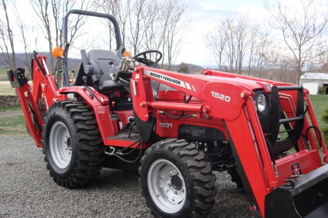 MF 1531
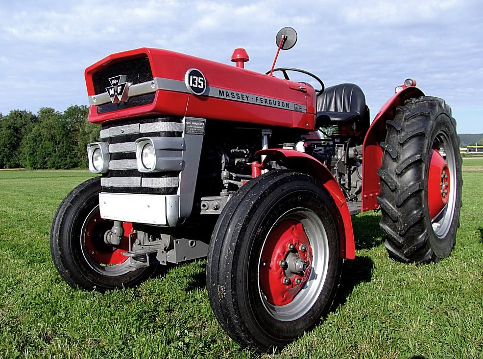 MF 135
 MF 1547
 MF 1635
________________________________________________________________________________________
 231
 231S
 235
 240
 241
________________________________________________________________________________________
_______________________________________________________________________________________
 255
 265
 274
 285
 375
________________________________________________________________________________________
________________________________________________________________________________________
 916X Loader
 921X Loader
 926X Loader
 931X Loader
 936X Loader
________________________________________________________________________________________
 941X Loader
 946X Loader
 951X Loader
 956X Loader
 988 Loader
________________________________________________________________________________________
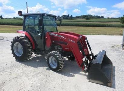 1655
 GS1705
 1742
 2635
 4608
________________________________________________________________________________________
 1080
 1100
 2615
 3050
 3060
________________________________________________________________________________________
 4708
 5455
 5450
 5610
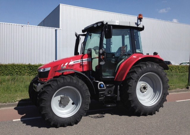 5613
________________________________________________________________________________________
 DL95 Loader
 DL100 Loader
 DL120 Loader
 DL125 Loader
 DL130 Loader
________________________________________________________________________________________
 DL135 Loader
 DL250 Loader
 DL260 Loader
 L90 Loader
 L100 Loader
________________________________________________________________________________________
 6499
 7480
 7618
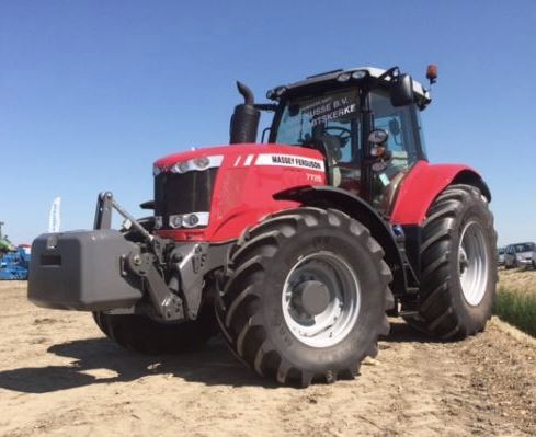 7726
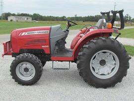 1533
________________________________________________________________________________________
 2604H
 2607H
 4455
 4610M
 4710
________________________________________________________________________________________
 L105E Loader
 L210 Loader
 1014 Loader
 1016 Loader
 1462 Loader
________________________________________________________________________________________
 1525 Loader
 1530 Loader
 232 Loader
 838 Loader
 848 Loader
________________________________________________________________________________________
 5712SL
 6713
 6715S
 7475
 7615
________________________________________________________________________________________
 7716
 7724
 8240
 8650
 8732
________________________________________________________________________________________
 246 Loader
 1036 Loader
 1038 Loader
 1080 Loader
 856 Loader