
________________________________________________________________________________
Massey Ferguson 5455, 5440 tractor gearbox- Output shaft
The bearings (28) (30) separated by a spacer (80) rotate the driving gear (29) on the output shaft. The bearings (79) (81) operate as axial stops. A single cone synchroniser allows range shifting between gears (29) (Hare) and (36) (Tortoise).
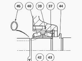
Preloading, or the clearance between the cones (39) (40) and their
respective cups (48) (37) is adjusted according to the thickness of the
circlip (49).
The output shaft transmits movement from the different ratios to the
rear axle transfer shaft. It is fitted on the lower transmission line at
the rear of the unit. It is supported at the front by a needle roller
bearing fitted in the layshaft bore and at the rear by two opposing
tapered roller bearings.
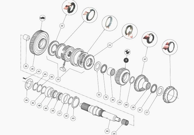
The shaft (44) supports:
- the driving gear (29) fitted idle onto the combined bearings (28)
(30);
- the idle-fitted gear (36) and ring (35) assembly;
- the Hare/Tortoise synchroniser (31), integral rotation by splines.
To ensure correct operation of the assembly depending on the load
applied to the MF 5440, 5455 transmission, several adjustments are
required:
- Shimming J3: via the circlip (49), this shimming cancels out the
clearance between the cones (39) (40) and their respective cup.
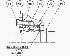
- Shimming J4: the shim(s) (38) positioned between the shoulder of the
shaft (44) and the cone (39) provide axial clearance for the gear (29).
- Shimming J5: the shim(s) (42) fitted between the cone (40) and the
shim (43) cancel out the axial clearance of the cones (39) (40) on the
shaft (44).
The GBA20 gearbox output shaft without creeper gears may be replaced by
two other shafts relating to the following options respectively: creeper
unit or super
creeper unit.
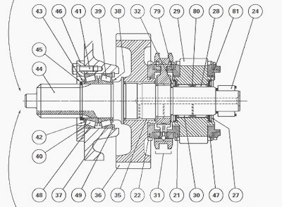
(21) Synchroniser cone (Hare) (22) Synchroniser cone (Tortoise) (24)
Needle roller bearing (27) Thrust washer (28) Needle roller bearing (29)
3rd driving gear
(Hare) (30) Needle roller bearing (31) Hare / Tortoise single cone
synchronizer (32) Thrust washer (35) Ring (36) Tortoise gear (37)
Bearing cup (38) Shim(s) (39)
Bearing cone (40) Bearing cone (41) Screw (42) Shim(s) (43) Shim (44)
Output shaft (45) Circlip (46) Stop plate (47) 3rd synchroniser cone
(48) Bearing cup (49)
Circlip (79) Needle roller bearing (80) Spacer (81) Needle roller
bearing
Disconnect the Massey Ferguson 5455, 5440 tractor between the gearbox
and the rear axle. Remove the selector cover plate. If necessary, remove
the screw.
Disassembling and reassembling the selector rail and the forks
The MF 5455, 5440 tractor is disconnected. Consequently, selector rail
removal is made easier by this separation which is to be made from the
rear side of the
gearbox housing. Apart from this point, the procedure remains unchanged.
If the tractor is fitted with a creeper unit, remove the pin, the
counter-nut, the adjustable lock, and the fork with the sleeve. If the
tractor is fitted with a super-creeper
unit, the fork and its lock are removed as described above, except for
the absence of the pin.
Remove the selector rail and the forks. Clean and check all components.
Replace those that are defective. Install the selector rail and the
forks. Depending on the
equipment, refit the sleeve, fork, adjustable lock and pin. To adjust
the fork.
Disassembling, reassembling and shimming the shaft
If the Massey Ferguson 5440, 5455 tractor is fitted with a creeper unit
or super-creeper unit, remove the unit. The bearing cones and cups are
to be paired if reused.
Remove the screws (41). Remove the stop plate (46). Remove the bearing
cup (48). Remove the circlip (45).
Remove the shim (43) and the shims (42). Remove the bearing cones (40)
(39). Remove the shims (38) and the cup (37). Remove the circlip (49).
Pull and remove
the shaft (44) backwards while holding the gear assembly.
Through the selector cover plate opening, take out:
- the synchroniser (31) and its rings;
- the Hare / Tortoise synchroniser cones (21) and (22);
- the gear assembly (29) and needle roller bearings (28) (30);
- the cone (47) and the 3rd synchroniser ring;
- the two needle roller bearings (79) (81);
- the thrust washers (27) (32). The synchroniser cones and rings are to
be paired if reused.
If necessary, remove the Tortoise gear (36). If work is necessary on
this gear, first remove the input unit in order to lift the gearbox
intermediate shaft to take out the
gear concerned through the selector cover plate opening. Remove the
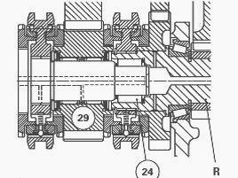
needle roller bearing (24), while marking the assembly direction.
Check and clean all components. Replace those that are defective.
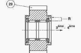
Position the needle roller bearing (24) in the bore of the layshaft "R",
taking care to position the
smaller diameter of the flexible ring towards the 3rd driving gear
(Hare) (29).
Install the shaft in the housing without the gears. Install a temporary
circlip (49), minimum thickness. Position the cup (37).
Slide cones (39) (40) and hold them against the shoulder of shaft (44)
by applying pressure by hand. Fill space Y between the rear of cone (40)
and the groove of
circlip (45) with shims (42) and shim (43) which will be placed against
circlip (45). Take a new circlip.
The circlip must be held closed in the groove under a slight pressure.
Install the cup (48) and the stop plate (46). Tighten screws (41) to a
torque of 25 - 35 Nm. For
gearboxes fitted with a creeper unit, use the unit plate to replace the
stop plate (46). Tighten the screws to a torque of 33.8 - 51.5 Nm.

Put the dial gauge feeler pin against the end of the shaft (44). Push
the shaft, while turning it alternately from right to left to correctly
"seat" the cones in the cups.
Set the dial gauge to zero. If the axial clearance is greater than 0.05
mm, set a definitive thickness of the circlip (49), to obtain J3 = -0.05
to +0.05 mm.
Remove the circlip (45). Remove the shim (43) and the shims (42). Remove
the screws (41) and the stop plate (46).
Remove: the cup (48); the bearing cones (40) (39), pairing them with
their cups; the cup (37); the temporary circlip (49) fitted; the shaft
(44).
Assembling the gears and the shaft
On the workbench, pre-assemble the 3rd driving gear (29) with the
synchroniser cones (21) and the 3rd gear (47) fitted with their
respective synchronizer ring. Fit
the bearings (79) (81) and washers (27)(32).
If removed, position the Tortoise gear (36) with its synchroniser ring
(22) into the housing. If the ring (35) of the Tortoise gear (36) is
damaged, replace the gear
assembly (the ring is rebored after fitting). Install the input unit.
In the housing, continue to fit:
- the 3rd driving gear (29) fitted with the needle roller bearings (28)
(30) (recess "R" facing towards the 3rd-4th synchroniser (Fig.6));
- the synchroniser (31). The needle roller bearings (28) (30) are
force-fitted and are separated by a spacer (80).
Install the output shaft (44) while holding the gear assembly.
Install the circlip (49) defined. Slide the cones and cups paired.
Install the stop plate (46). Tighten screws (41) to a torque of 25 - 35
Nm.
For MF 5440, 5455 gearboxes fitted with a creeper unit, use the unit
plate to replace the stop plate (46).
Tighten the screws to a torque of 33.8 - 51.5 Nm. Put the dial gauge
feeler pin against the end of the shaft (44).
Push the shaft, while turning it alternately from right to left to
correctly "seat" the cones in the cups.Set the dial gauge to zero.
Depending on the value read on the dial gauge, determine the thickness
of shims Z (38) to obtain: J4 = 0.20 to 0.40 mm.
Remove the screws (41) and the stop plate (46). Remove the cup (48).
Remove cones (40) (39).
Slide the required thickness of shims Z (38), and cones (39) (40) onto
the shaft.
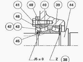
Carry out shimming to obtain the clearance J5 = 0. Using the thickness
of shims Y (42) (43), determine the thickness of shims Z (38) to obtain
the clearance J5 = Y
- Z. Install the cup (48) and the stop plate (46). Tighten screws (41)
to a torque of 25 - 35 Nm.
Slide the thickness of shims. Position the shim (43) on the circlip
groove side. Position the circlip (45): it must be held closed in the
groove under slight pressure.
Check that it is correctly positioned.
Install the creeper or super creeper Massey Ferguson 5455, 5440 gearbox
(depending on option). Manually check the rotation of the shaft and its
gears. Install the
forks and the selector rail. Install the selector cover plate, by first
checking for the presence of the screw.
Reconnect the tractor between the gearbox and the rear axle. Check: the
tightness of the systems; correct operation of electrical circuits.
Carry out a road test of
the controls. Check the tightness of the mating faces (selector cover
plate, gearbox on rear axle).
________________________________________________________________________________
________________________________________________________________________________________
 SPECS
SPECS LOADERS
 MAINTENANCE
 PROBLEMS
________________________________________________________________________________________
 MF 1523
 MF 1531
 MF 135
 MF 1547
 MF 1635
________________________________________________________________________________________
________________________________________________________________________________________
 231
231 231S
231S 235
235 240
240 241
241________________________________________________________________________________________
 255
255 265
265 274
274 285
285 375
375________________________________________________________________________________________
________________________________________________________________________________________
 916X Loader
 921X Loader
 926X Loader
 931X Loader
 936X Loader
________________________________________________________________________________________
 941X Loader
 946X Loader
 951X Loader
 956X Loader
 988 Loader
________________________________________________________________________________________
 1655
1655 GS1705
 1742
1742 2635
2635 4608
4608________________________________________________________________________________________
 1080
1080 1100
1100 2615
2615 3050
3050 3060
3060________________________________________________________________________________________
 4708
4708 5455
5455 5450
5450 5610
5610 5613
5613________________________________________________________________________________________
 DL95 Loader
 DL100 Loader
 DL120 Loader
 DL125 Loader
 DL130 Loader
________________________________________________________________________________________
 DL135 Loader
 DL250 Loader
 DL260 Loader
 L90 Loader
 L100 Loader
________________________________________________________________________________________
 6499
6499 7480
7480 7618
7618 7726
7726 1533
1533________________________________________________________________________________________
 2604H
2604H 2607H
2607H 4455
4455 4610M
4610M 4710
4710________________________________________________________________________________________
 L105E Loader
 L210 Loader
 1014 Loader
 1016 Loader
 1462 Loader
________________________________________________________________________________________
 1525 Loader
 1530 Loader
 232 Loader
 838 Loader
 848 Loader
________________________________________________________________________________________
 5712SL
 6713
6713 6715S
6715S 7475
7475 7615
7615________________________________________________________________________________________
 7716
7716 7724
7724 8240
8240 8650
8650 8732
8732________________________________________________________________________________________
 246 Loader
 1036 Loader
 1038 Loader
 1080 Loader
 856 Loader