
________________________________________________________________________________
Massey Ferguson 5460, 5465 gearbox - Power Shuttle
The housing of the GBA20 gearbox with Power
Shuttle consists of the following main components, in the order given:
- the Power Shuttle,
- the Speedshift input unit,
- the gearbox input gear train,
- the main gearbox,
- the creeper or super creeper gearbox (depending on option).
Power Shuttle
The Power Shuttle consists of two multidisc wet clutches (one for
forward operation and one for reverse operation).
These clutches are
located at the front of the
input unit, in front of the Speedshift unit.
The Power Shuttle is controlled by two proportional solenoid valves
operated by a lever located to the left under the steering wheel and
managed by the MF 5460,
5465 tractor electronic system.
Speedshift input unit
The Speedshift input unit consists of a hydraulic mechanism and an
epicyclic gear train.
It is located to the rear of the Power Shuttle.
It allows two gearbox input ratios to be obtained via a hydraulic
control unit and a solenoid valve.
Gearbox input gear train
The Massey Ferguson 5460, 5465 gearbox input gear train consists of two
meshed gears:
- a driving gear located at the rear of the input unit;
- a driven gear attached to the gearbox layshaft.
The input gear train transmits drive from the engine to the gearbox.
Main gearbox
The main gearbox consists of four basic gears and two speed ranges (Hare
and Tortoise), giving a total of eight ratios for each direction of
travel.
This transmission covers all usage requirements.
Creeper gearbox
The creeper gearbox is fitted to the gearbox output shaft.
It allows
slow travel. It operates at a ratio of 4/1.
It is controlled mechanically and should only be engaged when the
gearbox is in Tortoise range.
Super creeper gearbox
The super creeper gearbox is also fitted to the gearbox output shaft.
It consists of two epicyclic gear trains which allow a reduction ratio
of 14/1, and therefore allows very slow travel.
Like the creeper gearbox, it is controlled mechanically.
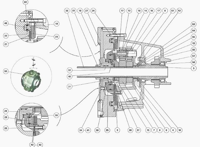
Massey Ferguson 5460, 5465 tractor gearbox with power shuttle
(3) Screw (4) Ring (5) Secondary shaft (6) Output sun gear (7) Input sun
gear (8) Planet gear pins (9) Planet carrier unit (10) Friction washer
(12) Double planet
gears (13) Unit (14) Spacers (15) Hub (16) Needle roller bearings (17)
Friction washers (18) Spring washer (Belleville) (19) Ring restrictor
(20) Thrust plate (21)
Brake disc (22) "O" ring (23) "O" ring (24) Screw (25) Hydraulic cover
plate (26) "O" ring (27) Front cover plate (28) Clutch piston (29) "O"
ring (30) Intermediate
plates (31) Rings (32) Needle roller bearings (33) Ring carrier (34)
Screw (36) Primary shaft (37) Circlip (38) Tab washer (39) Washer (40)
Ball bearing (41) Screw
(42) Discs (43) Spring washers (48) Brake piston (50) Planet carrier
assembly (30 kph version) (51) Screw (52) Cover plate (53) Shim(s) (54)
Bearing cup (56)
Driving gear (57) Bearing cup (58) Bearing cone
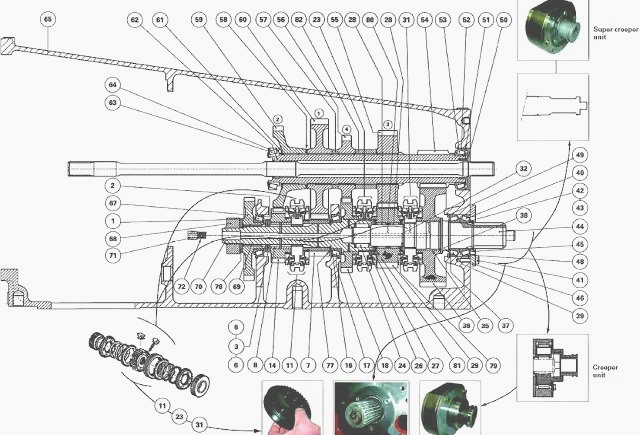
(1) Bearing cone (2) Bearing cup (3) Shim(s) (6) Splined washers (7) 1st
driving gear (8) Ring (11) 1st - 2nd double cone synchronizer (14) 2nd
driving gear (16)
Bearing cup (17) Bearing cone (18) 4th driving gear (23) 3rd - 4th
double cone synchronizer (24) Needle roller bearing (26) Circlip (27)
Washer (28) Needle roller
bearings (29) 3rd driving gear (Hare) (31) Hare / Tortoise double cone
synchronizer (32) Washer (35) Ring (36) Tortoise gear (37) Bearing cup
(38) Shim(s) (39)
Bearing cone (40) Bearing cone (41) Screw (42) Shim(s) (43) Shim (44)
Output shaft (45) Circlip (46) Stop plate (48) Bearing cup (49) Circlip
(50) Deflector (51)
Shim(s) (52) Bearing cup (53) Bearing cone (54) Intermediate shaft (55)
3rd driven gear (56) 4th driven gear (57) Spacer (58) Shim(s) (59) 2nd
driven gear (60) 1st
driven gear (61) Circlip (62) Needle roller bearing (63) Bearing cone
(64) Bearing cup (65) Gearbox housing (67) Input gear (68) Nut (69)
Layshaft (70) Snap ring
(71) Lubrication pipe (72) Spring (77) Washer with flat sections (78)
Tab washer (79) Needle roller bearing (80) Spacer (81) Needle roller
bearing (82) Spacer
MF 5460, 5465 power shuttle gearbox construction
The GBA20 gearbox with Power Shuttle consists of three gear trains
fitted to the: layshaft; intermediate shaft (or main shaft), output
shaft.
It allows eight basic synchronised gear ratios:
- four gear ratios: 1st, 2nd, 3rd and 4th;
- two range ratios: Hare and Tortoise.
Its main characteristic is its assembly of three double cone
synchronisers. The main gearbox consists of four synchronised gears. A
gear idle-mounted to the
output shaft and controlled by a synchroniser allows the four initial
gears to be doubled to obtain the eight basic gears.
The layshaft and the intermediate shaft are supported by tapered roller
bearings. The output shaft is fitted on two tapered roller bearings and
one needle roller
bearing. The layshaft bearing cups are fitted up against the housing.
All gears have helical teeth and are constantly meshed.
To ensure optimum gearbox reliability, the bearings are fitted: with
preload for the layshaft, with clearance for the intermediate shaft. The
output shaft may be set
either with a slight clearance or a slight preload.
The lubricating oil of the lower shaftline is supplied from the MF 5460,
5465 tractor hydraulic system via a 1.5 bar valve. It passes through a
channel in the layshaft
and output shaft. Radial bores direct the oil to the gears, bearings,
rings and synchronisers.
The splines of the Hare/Tortoise synchroniser hub are lubricated via a
radial bore on the output shaft. The oil flowing inside the intermediate
shaft lubricates the
tapered roller bearings and needle roller bearing (62). These bearings
are fitted respectively at the ends of the shaft.
Drive is transferred from the main gearbox by the driven gear (67) which
is permanently meshed with the driving gear for the input gear train
(Power Shuttle). The
driven gear (67) is splined to the layshaft (69). The two synchroniser
hubs (11) (23) are splined to the layshaft (69).
The 2nd driving gear (14) is freely mounted on a ring (8). The 1st (7)
and 4th (18) driving gears are freely mounted directly on the shaft. The
3rd driving gear (29) is
fitted on needle roller bearings (28). It is also fitted with a needle
roller thrust bearing on each of its faces to absorb any axial pressure.
The hub of the Hare / Tortoise synchroniser (31) is secured to the
output shaft (44). The driven gears (55), (56), (59) and (60) drive the
intermediate shaft (54) by
means of splines. The rear teeth of this shaft are constantly meshed
with the Tortoise gear (36) idle-mounted on the output shaft.
On GBA-20 gearboxes with Power Shuttle, the 1st - 2nd and 3rd - 4th gear
synchronisers and the Hare / Tortoise synchroniser are double cone type.
The double
cone synchroniser has the following advantages: improved reliability and
increased resistance to transmission loads.
Synchronisers (double cone)
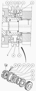
(1) Sliding coupler (2) Cone (brake) (3) Coupling flange (4) Ball
bearing (5) Pressure elements (6) Spring (7) Ring (8) Cone (brake)
Locked position
When the sliding coupler (1) moves towards the gear to be locked, it is
pressed against the ring (7) by the ball bearings (4) and pressure
elements (5).
The ring (7) transmits the pressure received to the cones (2) and (8) to
set a synchronisation speed.
When the synchronisation is set, the sliding coupler (1) can mesh and
silently lock with the teeth of the coupling flange (3).
Neutral position
The sliding coupler (1) is in the middle position. The ball bearings (4)
are pushed into the V groove of the sliding coupler by the pressure
springs (6).
The gears can turn freely on the shaft. In this neutral position, the
sliding coupler is locked by three balls held in place by the pressure
springs.
Overhaul
If the synchronisers (11), (23) and (31) are disassembled, check the
wear to the cones (2) and (8) in the following manner - Stack the
coupling flange (3), cones (2)
and (8) and ring (7). Correctly position the ring (7) on the cones (2)
and (8), turning it one way then the other several times and applying
manual pressure.
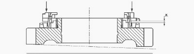
Using a set of shims, measure dimension X at three equidistant points.
Calculate the average of the three values and proceed as described
below, depending on the
result obtained. On a new synchroniser, dimension X must be 1.6 mm
minimum.
After operation, if X is less than or equal to 0.60 - 0.80 mm:
- replace the cones (2) and (8),
- check the measurement of X again, using the same process.
If dimension X is still incorrect, also replace the ring (7) or, if
necessary, the entire synchroniser.
Slow speed range (Tortoise)
Gear engagement is obtained by moving one of the synchroniser sliding
couplers (11) or (23) to join, in rotation, the layshaft (69) with one
of the freely-mounted
gears (1st, 2nd, 3rd, 4th). No matter what ratio is selected, the drive
is transmitted to the intermediate shaft (54).
The output shaft (44) is driven by the teeth machined on the
intermediate shaft, which is constantly meshed to the idle-mounted gear
(36). The low range (Tortoise)
is obtained by moving the synchroniser sliding coupler (31) backwards.
High speed range (Hare)
The high speed range is obtained by moving the synchroniser sliding
coupler (31) forwards, meshing the driving gear (29) and the output
shaft.
Consequently, in 3rd gear Hare, the intermediate shaft (54) is passive.
The other gears are obtained by moving the synchroniser sliding couplers
(11) or (23) as with the Tortoise range. Drive is transmitted to the
output shaft (44) by
driven gears (29) and (55).
________________________________________________________________________________
________________________________________________________________________________________
 SPECS
SPECS LOADERS
 MAINTENANCE
 PROBLEMS
________________________________________________________________________________________
 MF 1523
 MF 1531
 MF 135
 MF 1547
 MF 1635
________________________________________________________________________________________
________________________________________________________________________________________
 231
231 231S
231S 235
235 240
240 241
241________________________________________________________________________________________
 255
255 265
265 274
274 285
285 375
375________________________________________________________________________________________
________________________________________________________________________________________
 916X Loader
 921X Loader
 926X Loader
 931X Loader
 936X Loader
________________________________________________________________________________________
 941X Loader
 946X Loader
 951X Loader
 956X Loader
 988 Loader
________________________________________________________________________________________
 1655
1655 GS1705
 1742
1742 2635
2635 4608
4608________________________________________________________________________________________
 1080
1080 1100
1100 2615
2615 3050
3050 3060
3060________________________________________________________________________________________
 4708
4708 5455
5455 5450
5450 5610
5610 5613
5613________________________________________________________________________________________
 DL95 Loader
 DL100 Loader
 DL120 Loader
 DL125 Loader
 DL130 Loader
________________________________________________________________________________________
 DL135 Loader
 DL250 Loader
 DL260 Loader
 L90 Loader
 L100 Loader
________________________________________________________________________________________
 6499
6499 7480
7480 7618
7618 7726
7726 1533
1533________________________________________________________________________________________
 2604H
2604H 2607H
2607H 4455
4455 4610M
4610M 4710
4710________________________________________________________________________________________
 L105E Loader
 L210 Loader
 1014 Loader
 1016 Loader
 1462 Loader
________________________________________________________________________________________
 1525 Loader
 1530 Loader
 232 Loader
 838 Loader
 848 Loader
________________________________________________________________________________________
 5712SL
 6713
6713 6715S
6715S 7475
7475 7615
7615________________________________________________________________________________________
 7716
7716 7724
7724 8240
8240 8650
8650 8732
8732________________________________________________________________________________________
 246 Loader
 1036 Loader
 1038 Loader
 1080 Loader
 856 Loader