
________________________________________________________________________________
Massey Ferguson 5455, 5470 power shuttle gearbox – Shuttle
The Power Shuttle consists of two electrohydraulically controlled clutches. It is designed to enable direction of travel reversal under load.
The Power Shuttle transmits the drive from the engine to the layshaft
mounted on the front of the main gearbox by means of gears located
respectively at the rear of the unit and at the gearbox input. A lever
located to the left under the steering wheel, controls the Power
Shuttle.
Depending on the position selected by the operator (forward, neutral,
reverse), the lever manages the proportional solenoid valves of the
forward and reverse clutches by means of the Massey Ferguson 5455, 5470
tractor electronic system.
The solenoid valves are located at the front and to the right of the
gearbox on a clutch unit containing the Speedshift hydraulic control
system.
A filter element (60 microns) located under the selector cover plate,
upstream from the clutch unit, provides additional filtering of oil
supplying the solenoid valves (clutches, Speedshift). A potentiometer
sensor screwed to the gearbox housing sends information on shaft
rotational speed to the electronic system.
Shifting of any forward ratio to the corresponding reverse ratio, or
vice versa, is easy without declutching or stopping the tractor.
This "assisted" reversal enables gradual changing of the operating
direction, even at high travel speeds without abrupt changes in speed.
The clutches slow down tractor movement until the required speed is
reached so that the direction of travel can be reversed.
The conventional hydraulically operated clutch pedal is replaced by an
electrohydraulically operated manoeuvring pedal. This pedal modulates
the pressure in the forward or reverse clutches through the MF 5455,
5470 tractor electronic system and thus facilitates precise movements
such as implement hitching.
The forward and reverse clutches of the Power Shuttle are of different
design.
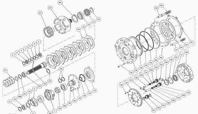
Forward clutch
The forward clutch consists of:
- a conventional multidisc wet clutch consisting of a bell (33), the
rear face of which is splined to assemble the input sun gear (53);
- an input shaft (19) crossing the spacer (4) which separates the engine
flywheel from the transmission oil.
- The shaft is constantly meshed with the damper secured to the engine
flywheel.
- It is splined so as to rotate with the clutch unit (18) which
comprises the intermediate plates (30) and the discs (29) in which the
piston (28) travels,
- a drive hub (27) comprising the discs (29), which is attached to the
primary shaft (55).
- The forward clutch is centred in the cover plate (38) of the reverse
clutch by the ball bearing (32).
Reverse clutch
The reverse clutch consists of:
- an epicyclic gear train consisting of three double planet gears (52)
and three single planet gears (59),
- a hydraulic braking device for the planet carrier (49),
- a cover plate (38) supporting the forward clutch and with an inner
face machined for fitting hydraulic components.
The double and single planet gears (52) (59) of the epicyclic gear train
mesh respectively on the input and output sun gears (53) (58). The pins
(50) are idle-mounted
and held in the planet carrier by plates (63).
A central drilled channel and radial ports supply lubrication to the
needle roller bearings (60). The planet carrier braking device consists
of an annular piston (39) and
a plate (43) that is loaded by springs (62) and discs (47) splined to
the planet carrier. The intermediate plates (46) are immobilised by the
pins (71).
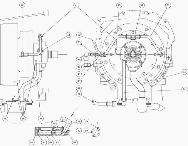
Fixed unit
The fixed unit (1) has two functions:
- it receives the low pressure supplying the forward clutch via the pipe
(74),
- it acts as a housing for the clutch lubrication and cooling pump.
The pipes (31) connecting the unit (1) and the cover plate (38)
lubricate the reverse clutch braking device. The shims (3) fitted
between the closing spacer (4) and
the fixed unit (1) provide axial clearance for the forward clutch.
MF 5455, 5470 tractor drive transmission
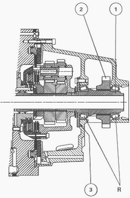
Drive from the Power Shuttle is transmitted to a mechanical component
located in the rear compartment of the input box. This component
comprises a secondary
shaft (1) attached to the gear (2) by splines.
The shaft is fitted on
two tapered roller bearings "R", and is supported by two bearings of the
input unit. The shims (3)
fitted between the cover plate and the unit are used to preload the
bearings.
Forward clutch
When the lever under the Massey Ferguson 5455, 5470 steering wheel is in
the Forward position, the relevant solenoid valve is activated and
supplies a pressure
that moves the piston (28).
This, in turn, compresses the intermediate
plates (30) and the discs (29) against the bell (33).
The movement from the engine to the gearbox complies with the following
drive train:
- input shaft (19) splined to unit (18),
- unit (18);
- intermediate plates (30);
- discs (29) compressed by the piston (28);
- hub (27),
- primary shaft (55),
- main gearbox layshaft via the input gear.
Simultaneously, the pressure applied behind the piston (39) of the
braking device drops and the planet carrier assembly (discs (47),
intermediate plates (46) and
epicyclic gear train) rotate freely.
During forward operation, the oil flow from the centre housing via the
pump (14) is directed towards the intermediate plates (30) and the discs
(29) via the ports of
the forward clutch unit (18) opened by movement of the piston (28).
At
the same time, lubrication of the braking device of the planet carrier
(discs (47) and
intermediate plates (46)) of the reverse clutch is interrupted.
Reverse clutch
When the previously mentioned lever is moved from the Forward to Reverse
position, the solenoid valve concerned is activated and supplies the
piston (39) of the
braking device of the planet carrier.
The piston then presses on plate
(43) which compresses discs (47) and the intermediate plates (46)
against the front cover
plate of the input unit and stops the rotation of the planet carrier
assembly.
The drive from the engine is directly transmitted to the bell (33)
splined to the input sun gear (53), without passing through the discs
and intermediate plates of the
forward clutch. Simultaneously, the oil pressure in the chamber of the
piston (28) drops and frees the discs (29) and intermediate plates (30).
The input sun gear (53) then drives the double planet gears (52) freely
mounted on the pins (50) which, in turn, drive the single planet gears
(59) thus reversing the
rotation of the output sun gear (58) splined to the primary shaft (55).
The primary shaft then transmits the drive from the engine to the MF
5455, 5470 main gearbox layshaft via the input gear. A valve screwed to
the top section of the
cover plate (38) creates a small permanent bleed starting from 13 bar to
provide an automatic bleed of the piston supply system (39).
Lubrication
As the piston (39) moves, it operates spools (44) that act as valves and
compress springs (45) via the plate (43).
The spools have a drilled
centre channel and
radial ports, allowing oil to flow to the channels in the cover plate
(38) and the channels in the front cover plate of the input unit, thus
lubricating the discs (47) and the
intermediate plates (46).
Lubrication of the mechanical components of the epicyclic gear train is
via the lubricating system of the input unit. At the same time, the
lubricating oil flow to the
discs (29) and intermediate plates (30) of the forward clutch is
interrupted, thus preventing any possible drive to the discs due to a
"drag" effect.
Neutral position
In neutral position, the supply to the solenoid valves is cut, placing
the forward and reverse clutches at rest and eliminating transmission of
the engine drive to the
gearbox. The lubrication flow is also interrupted.
The pressure inside
the system opens the valve and directs the oil to the housing. After
changing a solenoid valve
or its coil, the Power Shuttle hydraulic unit, the unit or one of its
components or the electronic controller, it is necessary to calibrate
the clutches.
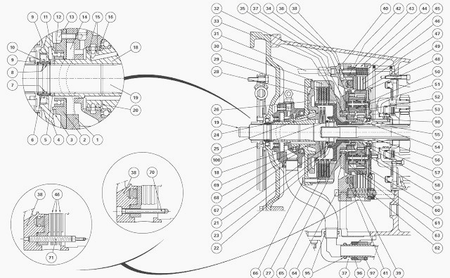
(1) Pump unit (2) Pump cover plate (3) Shim(s) (4) Spacer (5) Locking
ring (6) Splined ring (7) "O" ring (8) Anti-extrusion rings (9) Snap
rings (10) Seal (11) Circlip
(12) Ball bearing (13) Screw (14) Lubricating pump (15) Seal rings (16)
Ring (17) Centring pin (18) Forward clutch unit (19) Input shaft (20)
Pin (21) Circlip (22) Ball
bearing (23) Snap ring (24) Seal (25) Belleville washers (26) Index
holes (27) Drive hub (28) Forward clutch piston (29) Forward clutch
discs (30) Forward clutch
intermediate plates (31) Lubrication pipe (32) Ball bearing (33) Forward
clutch bell (34) Planet carrier cover plate (35) Rivets (36) Seal (37)
Cover plate (38) Reverse
clutch cover plate (39) Reverse clutch piston (40) Rivets (41) Seal (42)
Seal (43) Plate (44) Spools (45) Springs (46) Reverse clutch
intermediate plates (47)
Reverse clutch discs (48) Ring restrictor (49) Planet carrier (50)
Planet gear pins (51) Spacers (52) Double planet gears (53) Input sun
gear (54) Snap ring (55)
Primary shaft (56) Snap ring (57) Ball bearing (58) Output sun gear (59)
Single planet gears (60) Needle roller bearings (61) Snap rings (62)
Springs (63) Stop plates
(64) Screw (65) Snap ring (66) Screw (67) "O" ring (68) Ball bearing
(69) Seal (70) Screw (71) Pins (72) Union (73) 1.5 bar valve (74) Pipe
(75) "O" rings (76) Pipe
(77) Screw (78) Pipe (79) Screw (80) Flange (81) Seal (82) Strainer (83)
Cover plate (84) Plug (85) Seal (86) Pipe (87) Pipe (88) Transfer pipe
(89) Seal (Loctite)
(90) Diagnostics connector (lubrication) (91) Union (92) "O" rings (93)
Union (94) Pipe (95) "O" rings (96) Dust seal (97) Screw (98) Snap ring
(99) Screw (100) Ring
(101) Elbow union
________________________________________________________________________________
________________________________________________________________________________________
 SPECS
SPECS LOADERS
 MAINTENANCE
 PROBLEMS
________________________________________________________________________________________
 MF 1523
 MF 1531
 MF 135
 MF 1547
 MF 1635
________________________________________________________________________________________
________________________________________________________________________________________
 231
231 231S
231S 235
235 240
240 241
241________________________________________________________________________________________
 255
255 265
265 274
274 285
285 375
375________________________________________________________________________________________
________________________________________________________________________________________
 916X Loader
 921X Loader
 926X Loader
 931X Loader
 936X Loader
________________________________________________________________________________________
 941X Loader
 946X Loader
 951X Loader
 956X Loader
 988 Loader
________________________________________________________________________________________
 1655
1655 GS1705
 1742
1742 2635
2635 4608
4608________________________________________________________________________________________
 1080
1080 1100
1100 2615
2615 3050
3050 3060
3060________________________________________________________________________________________
 4708
4708 5455
5455 5450
5450 5610
5610 5613
5613________________________________________________________________________________________
 DL95 Loader
 DL100 Loader
 DL120 Loader
 DL125 Loader
 DL130 Loader
________________________________________________________________________________________
 DL135 Loader
 DL250 Loader
 DL260 Loader
 L90 Loader
 L100 Loader
________________________________________________________________________________________
 6499
6499 7480
7480 7618
7618 7726
7726 1533
1533________________________________________________________________________________________
 2604H
2604H 2607H
2607H 4455
4455 4610M
4610M 4710
4710________________________________________________________________________________________
 L105E Loader
 L210 Loader
 1014 Loader
 1016 Loader
 1462 Loader
________________________________________________________________________________________
 1525 Loader
 1530 Loader
 232 Loader
 838 Loader
 848 Loader
________________________________________________________________________________________
 5712SL
 6713
6713 6715S
6715S 7475
7475 7615
7615________________________________________________________________________________________
 7716
7716 7724
7724 8240
8240 8650
8650 8732
8732________________________________________________________________________________________
 246 Loader
 1036 Loader
 1038 Loader
 1080 Loader
 856 Loader