________________________________________________________________________________
MF 5435, 5445 mechanical reverse shuttle gearbox – Selector cover plate
On Massey Ferguson 5435, 5445 tractors with mechanical reverse shuttle,
the selector cover plate is fitted to the right-hand side of the gearbox
housing.
It has two levers:
- a front lever to control the mechanical reverse shuttle;
- a rear lever to select the four basic gears and to indicate to the tractor electronic system when it is in neutral position for Hare / Tortoise range shifting. Hare / Tortoise range shifting is carried out via a pulse button integrated into the transmission lever handle.
The action is validated when the
lever is in neutral. A sensor "C"
fitted to the selector cover plate buzzes to warn the user that a gear
is engaged when the hand brake is on.

Hare / Tortoise fork locking and gear control
(1) Plug or oil return port (2) Earthing lug (3) Screw (4) Centring
screws (5) Plug (6) Stud and nut (9) Selector cover plate (13) Gear
control finger and pin (14) Speed
grid (15) Screw (16) Support (17) Locating ring (18) Ball bearing (19)
Screw (20) Spring (21) Washer (22) Circlip (25) Seal (26) Guide ring
(27) Seal (28) Neutral position switch (31) Plunger (33) Washer (34)
Toggle switch (35) Indexing rod

MF 5435, 5445 Tractor Mechanical reverse shuttle control
(25) Seal (26) Guide ring (36) Finger (37) Pin (38) Set screw (39) Guide
ring

Hare / Tortoise fork locking and gear control
(2) Transmission lever (13) Control finger and pin (31) Plunger (34)
Toggle switch (35) Indexing rod

Mechanical reverse shuttle control
(1) Control lever (2) Selector (5) Rod (6) Fork (36) Finger (37) Pin
Massey Ferguson 5435, 5445 Transmission lever
Selecting 1st - 2nd ratios
The transmission lever (2) operates lever L and engages the finger (13)
in the 1st - 2nd fork.
The first ratio is obtained by moving lever L upwards and the second
ratio downwards.
Simultaneously, the toggle switch (34) secured to pin A pivots and moves
the plunger (31) thus locking the indexing rod (35) and the
Hare/Tortoise fork.
Selecting 3rd - 4th ratios
In this configuration, the finger (13) secured to pin A is engaged in
the 3rd - 4th gear fork.
The third ratio is obtained by moving lever L upwards and the fourth
ratio downwards.
The locking principle of the indexing rod (35) and Hare/Tortoise fork is
identical to that used for the 1st - 2nd ratios.
Hare/Tortoise range
Hare/Tortoise range shifting is validated when the transmission lever is
in the Neutral position.
If the button located on the transmission lever
handle is activated and
if switch (28) has confirmed the Neutral position of the lever, the
electronic system of the MF 5435, 5445 tractor allows voltage to be
supplied to or cut off from the
Hare/Tortoise solenoid valve in order to obtain movement of the fork in
the required range.
Hare position
The Hare/Tortoise solenoid valve, fitted on the lower part of the
right-hand cover plate opens and supplies chamber "a" located behind
piston (1).
The piston moves forward, and pushes the fork (Hare / Tortoise).
The oil contained in chamber "b" is discharged into the Tortoise
channel, and returns into the 17 bar system.

Tortoise position
When the pulse switch is activated again, the solenoid valve is closed,
and the pressure drops in chamber "a".
The piston (1) moves back due to the 17 bar pressure exerted on the
annular face.
The oil contained in chamber "a" returns to the housing via the Hare
channel and the solenoid valve.
Identification and function of Hare / Tortoise range locking elements
Toggle switch
This is one of the main elements of the Hare / Tortoise range locking
system.
It is freely mounted on pin A and pivots with it by means of a flat
section.
Function - It moves the plunger (31) towards the indexing rod (35) and
locks the latter during gear engagement.
Via its opposite face it controls the neutral position of pin A
(transmission lever) using the switch (28).
Indexing rod
At one end there are two different locking grooves:
- the narrow groove: Hare position;
- the wide groove: Tortoise position.
The other end is designed to house the stop of the Hare / Tortoise fork.
Function - It avoids any unwanted reverse movement of the Hare /
Tortoise fork in case of electronic or hydraulic malfunction.
Plunger
Spherically shaped at each end, it moves between the toggle switch (34)
and indexing rod (35).
Function - It acts as the system lock, whatever range is engaged.
Switch
It is controlled by the toggle switch.
Function - It informs the Massey Ferguson 5435, 5445 tractor electronic
system when the transmission lever is in neutral position.
Reverse shuttle lever
The reverse shuttle function is activated when the lever (1) is shifted
either upwards (forward travel) or downwards (reverse travel).
When the lever (1) is shifted, the rod (5) and pin (37) rotate partly, the latter being secured to the finger (36). The finger (36) then moves the mechanical reverse shuttle fork (6) and selector (2).
________________________________________________________________________________
 SPECS
 LOADERS
 MAINTENANCE
 PROBLEMS
________________________________________________________________________________________
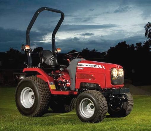 MF 1523
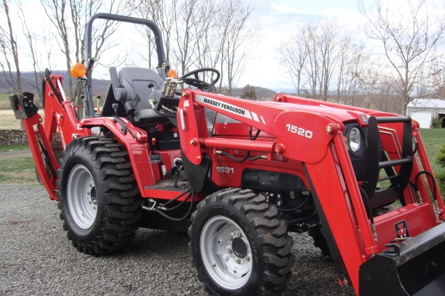 MF 1531
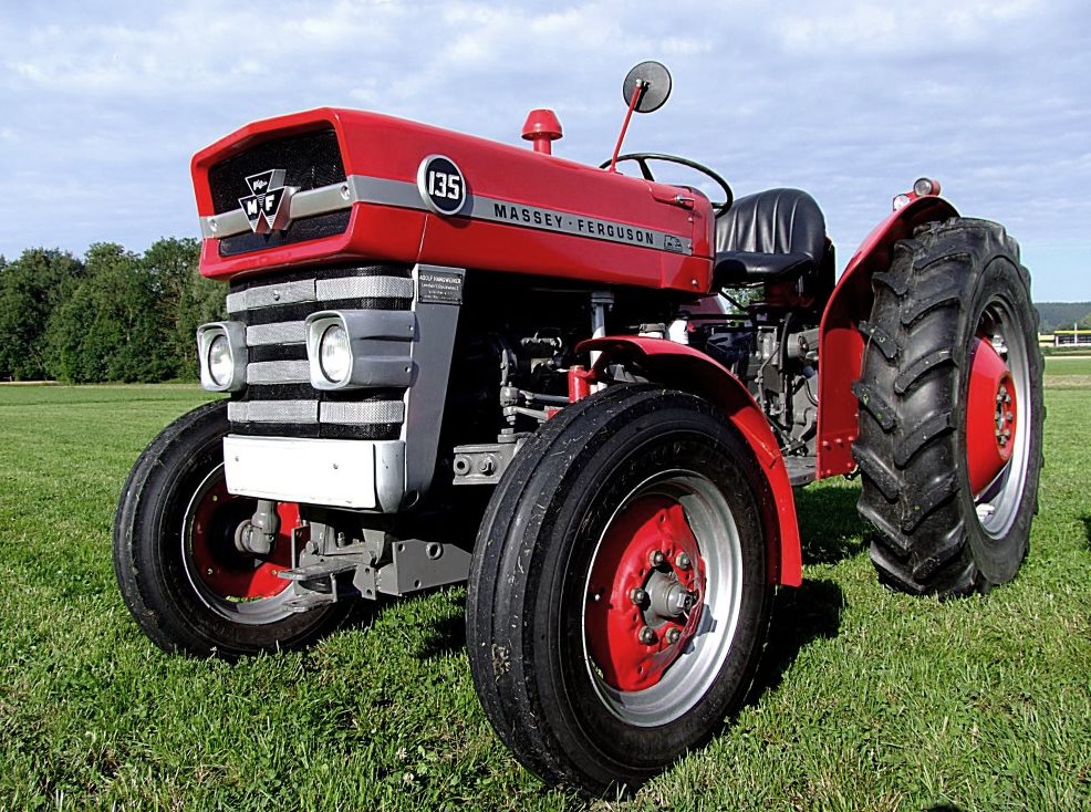 MF 135
 MF 1547
 MF 1635
________________________________________________________________________________________
 231
 231S
 235
 240
 241
________________________________________________________________________________________
_______________________________________________________________________________________
 255
 265
 274
 285
 375
________________________________________________________________________________________
________________________________________________________________________________________
 916X Loader
 921X Loader
 926X Loader
 931X Loader
 936X Loader
________________________________________________________________________________________
 941X Loader
 946X Loader
 951X Loader
 956X Loader
 988 Loader
________________________________________________________________________________________
 1655
 GS1705
 1742
 2635
 4608
________________________________________________________________________________________
 1080
 1100
 2615
 3050
 3060
________________________________________________________________________________________
 4708
 5455
 5450
 5610
 5613
________________________________________________________________________________________
 DL95 Loader
 DL100 Loader
 DL120 Loader
 DL125 Loader
 DL130 Loader
________________________________________________________________________________________
 DL135 Loader
 DL250 Loader
 DL260 Loader
 L90 Loader
 L100 Loader
________________________________________________________________________________________
 6499
 7480
 7618
 7726
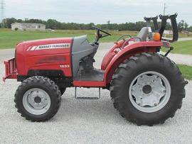 1533
________________________________________________________________________________________
 2604H
 2607H
 4455
 4610M
 4710
________________________________________________________________________________________
 L105E Loader
 L210 Loader
 1014 Loader
 1016 Loader
 1462 Loader
________________________________________________________________________________________
 1525 Loader
 1530 Loader
 232 Loader
 838 Loader
 848 Loader
________________________________________________________________________________________
 5712SL
 6713
 6715S
 7475
 7615
________________________________________________________________________________________
 7716
 7724
 8240
 8650
 8732
________________________________________________________________________________________
 246 Loader
 1036 Loader
 1038 Loader
 1080 Loader
 856 Loader