
________________________________________________________________________________
MF 5410, 5450 mechanical reverse shuttle gearbox - Selector cover plate repair
Removing and install the cover Plate
Immobilise the Massey Ferguson 5410, 5450 tractor. Chock the left rear
wheel. Apply the hand brake. Chock between the frame and the front axle.
Drain the gearbox. Raise the rear right-hand side of the tractor with a suitable jack. Remove the wheel. Place an axle stand in position.
Remove the
right-hand step and any
surrounding parts that might hinder removal of the cover plate.
Removing the gear control
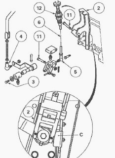
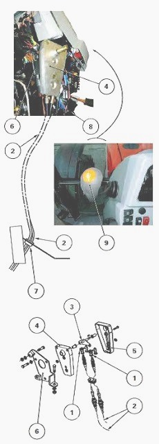
Disconnect the harness of sensor "C".
Remove the ball joint (4).
Remove the screw (3).
Remove the pins (11).
Disconnect the ball joint (5).
Mark the adjustment of the cable (6). Slightly loosen the top nut
(12). Separate the cable from the support (2).
Removing the reverse shuttle control
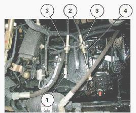
Disconnect the clips (1). Mark the adjustment of the cables (2).
Loosen the lower nuts (3). Separate the cables from the support (4).
Disconnect the control cable (1) from the creeper or super creeper unit on MF 5410, 5450 tractors fitted with this option.
Remove the screws (3)
(4) and the nut (6),
marking the location of the earthing lug (2) and centring screws (4). If
fitted, remove the support (2) of the creeper or super creeper unit
control cable. Release and
remove the selector cover plate.
Clean the mating face of the gearbox and the cover plate. Install: the
3rd - 4th fork in ratio 3; the Hare / Tortoise range fork in Hare
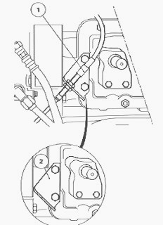
position. Before refitting the cover
plate, check that the screw (1) is present.
Lightly smear the mating face of the gearbox housing with a sealing
product such as Loctite 510 or equivalent. Turn the finger (13) to the
left. Install the indexing rod
A in Hare position. Move the selector (2) and finger (36) to neutral
position.
Install the cover plate on the Massey Ferguson 5410, 5450 gearbox,
ensuring that:
- the finger (13) is positioned correctly in the forks;
- the finger (36) is engaged in the selector (2).
Install the creeper or super creeper control cable support (if fitted).
Install the earthing lug (2). Install and tighten the screws (3) (4) and
the nut (6) to a torque of 50 -
70 Nm.
The centring screws (4) must be fitted as shown. Depending on the
option, reconnect and adjust the creeper or super creeper control.
Reconnect the
harness on the neutral position switch.
Reconnect:
- the gear control and sensor "C".
- the reverse shuttle control.
Using a grease gun, lubricate the joints of the gear control on the
selector cover plate.
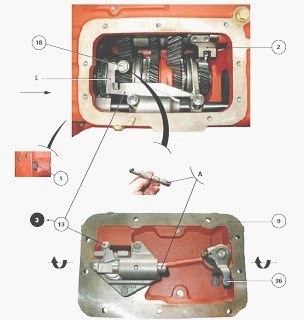
A - Indexing rod for locking the Hare/Tortoise fork, L - Synchronisation
of the Hare/Tortoise mechanism in Hare range, (3) Engaged gear (e.g. 3rd
gear) (1) Screw
(9) Selector cover plate (13) Finger (18) Locking stop
Check the shifting of all gears and the reverse shuttle. If required,
adjust the controls. Check the operation of the MF 5410, 5450 mechanical
reverse shuttle
gearbox. As required, Install any components removed previously from
around the cover plate.
Install the wheel. Tighten the nuts to a torque of 400 - 450 Nm.
Top up the oil level in the housings. Check it using the gauge at the
rear of the centre housing.
Remove the chocks between the frame and the front axle. Release the hand
brake.
Check that the buzzer of the safety sensor vibrates correctly (ignition
on, hand brake on and gear engaged).
Start the engine. When on the road, check:
- shifting up and down of the gear ratios;
- operation of the Hare / Tortoise range with the pulse button located
on the lever;
- operation of the reverse shuttle in the forward and reverse positions.
Check the tightness of the selector cover plate mating face and of the
hydraulic unions.
Disassembling and reassembling the gear selector and reverse shuttle
mechanisms
Take off the cover plate. Secure it in a vice fitted with protective
jaws.
Gear selector mechanism
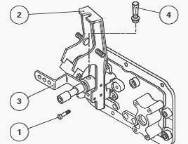
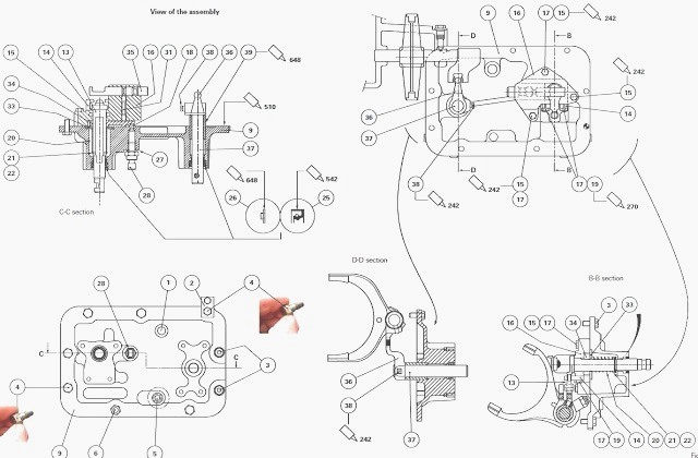
Remove the screws (1). Remove the key (4) and selector (3). Remove the
support (2) from the cover plate.
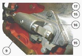
Remove the screws (15). Separate the cover plate (9) and support (16)
comprising the gear control assembly.
If necessary, extract the locating rings (17).
On the cover plate
Take off the Neutral position switch (28). Recover the seal (27) and
ball bearing (18).
Extract and discard the seal (25).
On the support
Take off the circlip (22), washer (21) and remove the spring (20).
Release the washer (33) and toggle switch (34), marking its position and
profile.
Recover the plunger (31). Extract the indexing rod (35).
If necessary:
- remove the screws (19);
- remove the speed grid (14);
- extract the locating rings (17).
Reverse shuttle selector mechanism
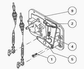
Take out the set screw (4). Remove the rod (5).
Remove the screws (1). Separate the support (2) from the cover plate
(9).
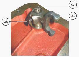
Take out the set screw (38). Remove the finger (36) and pin (37) from
the cover plate.
On the cover plate
Remove any plugs screwed to the cover plate.
Extract and discard the seal (25).
Gear selector mechanism
If it was necessary to replace the guide ring (26), lightly smear its
rim with Loctite 648 or equivalent. Install it up against the shoulder
of the cover plate.
On the support
If necessary:
- fit the locating rings (17),
- refit the speed grid (14) on the support (16),
- tighten the screws (19), lightly smeared with Loctite 270 or
equivalent, to a torque of 29 - 37 Nm.
Check that:
- the plunger (31) and indexing rod (35) move freely in the support
(16),
- the flat section of the toggle switch (34) slides normally on the
finger (13).
Slide the pin of the finger (13) into the support (16). Turn the toggle
switch (34) as required. Install it onto the finger (13). Fit the washer
(33). Install the spring (20)
and washer (21).
Install the circlip (22). Slide the plunger (31) into
its cavity in the support (16). Place the finger (13) in the Neutral
position. Turn the indexing rod (35)
as required and Install it.
On the cover plate
Check that the locating rings (17) are present. Install the gear control
and support (16) assembly on the cover plate (9).
Lightly smear the thread of the screws (15) with Loctite 242 or
equivalent. Tighten to a torque of 29-37 Nm.
Protect the lip of the seal (25) by surrounding the cylindrical end of
the finger (13) with a flexible protection.
Lightly smear the external rim of the seal with Loctite 542 or
equivalent and slide it onto the protection.
Remove the safety shield. Install the seal onto the cover plate using a
suitable fixture.
Check that finger (13) is in the Neutral position. Slide the ball
bearing (18) into the depression on the toggle switch (34).
Checking the Neutral position switch
Press manually on the button located at the end of the switch. Release
the pressure and check that the button returns freely to its initial
position.
Repeat the
operation several times. The check can be carried out using a
multimeter.
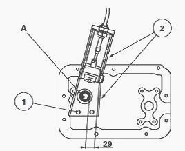
Install the switch complete with its seal and tighten to a torque of 15
- 25 Nm. Install the support (2), allowing a distance of 29 mm between
the support and the 22
mm diameter of pin A.
Lightly smear the screws (1) with Loctite 270 and
tighten them to a torque of 25 - 35 Nm. This dimension must be met for
the sensor to
operate correctly. Install the selector (3). Install and tighten the
key.
Checking the locking system of the indexing rod
In the grid (14), move the finger (13) from 1st to 4th ratio using the
selector (3) and manually check for the correct locking of the indexing
rod in each of its positions.
This indexing rod is linked to the Hare/Tortoise fork by an adjustable
stop. If the replacement of certain components of the locking system was
necessary, it is
mandatory to readjust this stop.
MF 5410, 5450 gearbox reverse shuttle selector mechanism
Assemble the finger (36) and pin (37). Lightly smear the thread of the
set screw (38) with Loctite 242 or equivalent.
Tighten this screw to a torque of 28 - 43 Nm.
If the guide rings (26) and (39) of the pin (37) needed replacing,
lightly smear the rim of each ring with Loctite 648 or equivalent.
Fit these rings up against their respective shoulders on the cover
plate. Install the support (2) on the cover plate (9).
Lightly smear the thread of the screws (1) with Loctite 270 or
equivalent. Tighten these screws to a torque of 25 - 35 Nm.
Slide the pin (37)/finger (36) assembly into the relevant bore on the
cover plate.
Protect the lip of the seal (25) by surrounding the cylindrical end of
the pin (37) with a flexible protection.
Lightly smear the external rim of the seal with Loctite 542 or
equivalent. Slide the seal onto the protection.
Remove the safety shield. Insert the seal into the cover plate using a
suitable fixture.
Install the rod (5). Lightly smear the thread of the set screw (4) with
Loctite 242 or equivalent.
Tighten this screw to a torque of 30-35 Nm. Remove the cover plate from
the vice. Refit it on the gearbox.
Assembling and adjusting the gear linkage and reverse shuttle control
cables
Gear linkage - cab side
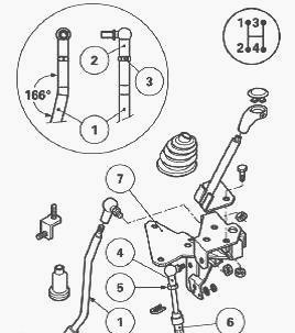
On the end of the rod (1) shaped with an angle of 166°, position the
ball joint (2). Tighten the nut (3). Tighten the ball joint (4) up
against the cable (6). Tighten the nut
(5). Place the support (7) on a workbench.
On the support, fit and tighten:
- the transmission lever.
- the previously prepared rod and cable.
Install and secure the support onto the right-hand wheel housing of the
cab. During this operation, ensure the rod and cable are inserted
through the holes in the
compartments. Install the shield rings.
Gear linkage - selector cover plate side
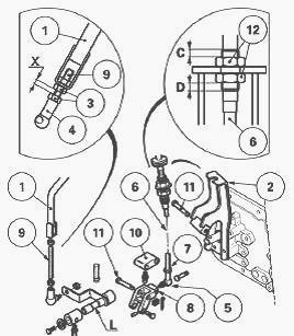
Screw the threaded rod (9) (fitted with nuts (3) and the ball joint (4))
onto the rod (1).
Tighten the ball joint (5) up against the cable (6). Tighten the nut
(7).
Tighten and lock the other end of the ball joint (5) onto the cam (8).
On the previously fitted support (2) and lever "L", position the cam (8)
and its extension block (10).
Install the pins (11), and lock them in place with new pins. Install the
ball joint (4) on the lever L. Install the washer and tighten the
locknut.
Adjusting the rod (1) - Turn the threaded rod (9) and ball joint (4) to
obtain a dimension X of 17 ± 1 mm between the two nuts (3) when they are
tightened.
Adjusting the cable
Adjust the sheath end to balance (as far as possible) dimensions "C" and
"D". Tighten the nuts (12) without altering the adjustment.
Checking the proper engagement of each gear ratio and the position of
the lever in the opening of the console.
This check should be performed with the gaiter of the Massey Ferguson
5410, 5450 transmission lever temporarily removed.
Engage each gear ratio. During this operation, check that the lever is
never closer than 5 mm from the edge of the console.
Results
Lever movement is not hindered in any way by the console - Adjustment is
correct. Position the gaiter.
Lever movement is hindered by the console - The lever is positioned
incorrectly.
Readjust the rod (1) on the selector cover plate side in accordance with
the following instructions:
- If the problem concerns the 1st or 3rd gear, reduce dimension X.
- If the problem concerns the 2nd or 4th gear, increase dimension X.
- If the problem concerns lateral movement of the lever between the 1-2
and 3-4 gear paths (Neutral position), adjust the cable sheath end (6)
(dimensions C and D).
Tighten the nuts (12).
Reverse shuttle control cables - cab side
The assembled unit (4) and cables (2) are entered in the catalogue as a
complete assembly under a single reference. However, this assembly
comprises a number
of parts, most of which are available as spare parts.
Screw the clevises (1) level with the threaded end of the cables (2).
Install the clevises on the swinging lever (3).
Install the clips. Tighten the nuts. Slide the cable sheath ends into
the slots provided on the unit (4).
Position and tighten the cover plate
(5).
Assemble the support (6) on the unit (4). Attach the unit (4) / support
(6) assembly to the base of the instrument panel (8).
Ensure the cables are inserted into the hole in the cab floor. Position
the feed-through conduits (7).
Position the floor mat. Install the instrument panel cover and related
components.
Position the reverse shuttle lever. Tighten the screw after smearing it
with Loctite 242 or equivalent. Install the gaiter.
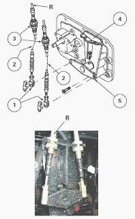
Reverse shuttle control cables – selector cover plate side
Screw the clevises (1) level with the threaded end of the cables (2).
Slide the sheath ends (3) into the slots provided on the support (4).
The cable fitted with an adhesive colour strip must be fitted in the
left-hand slot in the support (4). The adhesive strip can be stuck
anywhere on the cable and is
represented by the letter R.
If the adhesive strip is missing, position the cables in the slots so
that the shuttle lever position corresponds with the direction of
movement of the MF 5410, 5450
tractor:
- forward: lever pointing upwards
- reverse: lever pointing downwards
Place the rod (5) in neutral.
Install the clevises (1) to the rod. Tighten the clevis nuts.
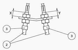
Cable adjustment
Gradually and alternately adjust the tension of the cables (2) using the
sheath ends (3) to achieve identical X and Y values, if possible.
Tighten the nuts without altering the adjustment.
Check
Alternately engage the forward and reverse positions.
For each ratio, check that the rod (5) locks correctly without excessive
cable tension.
Carry out a road test of the gear controls and reverse shuttle.
________________________________________________________________________________
________________________________________________________________________________________
 SPECS
SPECS LOADERS
 MAINTENANCE
 PROBLEMS
________________________________________________________________________________________
 MF 1523
 MF 1531
 MF 135
 MF 1547
 MF 1635
________________________________________________________________________________________
________________________________________________________________________________________
 231
231 231S
231S 235
235 240
240 241
241________________________________________________________________________________________
 255
255 265
265 274
274 285
285 375
375________________________________________________________________________________________
________________________________________________________________________________________
 916X Loader
 921X Loader
 926X Loader
 931X Loader
 936X Loader
________________________________________________________________________________________
 941X Loader
 946X Loader
 951X Loader
 956X Loader
 988 Loader
________________________________________________________________________________________
 1655
1655 GS1705
 1742
1742 2635
2635 4608
4608________________________________________________________________________________________
 1080
1080 1100
1100 2615
2615 3050
3050 3060
3060________________________________________________________________________________________
 4708
4708 5455
5455 5450
5450 5610
5610 5613
5613________________________________________________________________________________________
 DL95 Loader
 DL100 Loader
 DL120 Loader
 DL125 Loader
 DL130 Loader
________________________________________________________________________________________
 DL135 Loader
 DL250 Loader
 DL260 Loader
 L90 Loader
 L100 Loader
________________________________________________________________________________________
 6499
6499 7480
7480 7618
7618 7726
7726 1533
1533________________________________________________________________________________________
 2604H
2604H 2607H
2607H 4455
4455 4610M
4610M 4710
4710________________________________________________________________________________________
 L105E Loader
 L210 Loader
 1014 Loader
 1016 Loader
 1462 Loader
________________________________________________________________________________________
 1525 Loader
 1530 Loader
 232 Loader
 838 Loader
 848 Loader
________________________________________________________________________________________
 5712SL
 6713
6713 6715S
6715S 7475
7475 7615
7615________________________________________________________________________________________
 7716
7716 7724
7724 8240
8240 8650
8650 8732
8732________________________________________________________________________________________
 246 Loader
 1036 Loader
 1038 Loader
 1080 Loader
 856 Loader