
________________________________________________________________________________
MF 5430, 5450 mechanical reverse shuttle gearbox - Selector rail repair
Disassembly and reassembly operation
Creeper gear fork
Remove the rear right-hand wheel. Chock the Massey Ferguson 5430, 5450
tractor. Disconnect the creeper unit control cable on the rear axle.
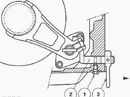
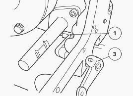
Remove the selector cover plate. Take out the plugs (1), the springs (2)
and the detent plungers (3) to release the selector rail.
Remove the hydraulic cover plate(s). Remove the screw (1). Pull the rod
(2) and the lever (3) outwards to release the finger of the fork.
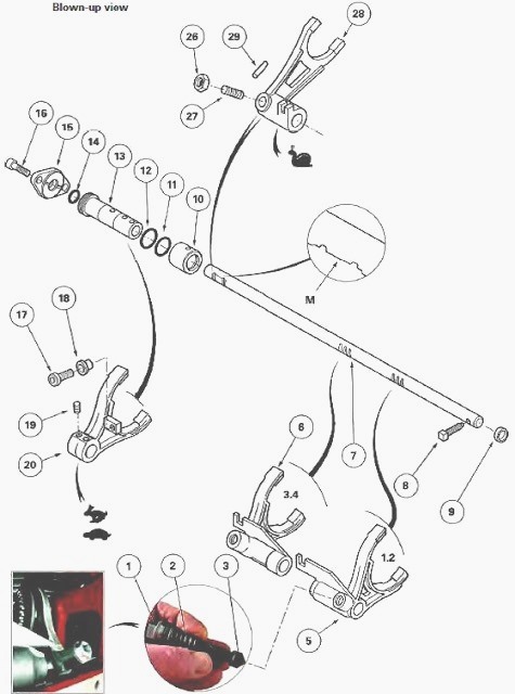
Unscrew the nut (26) and the locking screw (27) on the fork (28). Take
out the set screw (8).
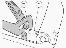
Turn the selector rail (7) and drive out the pin (29) without dropping
it into the housing. Move the selector rail forward.
Removing the pin (1) from the coupling sleeve (2) on a 2WD or 4WD Massey
Ferguson 5430, 5450 tractor.
Depending on the angular position of the coupling sleeve located between
the gearbox output shaft and the pinion, the pin is accessible or
inaccessible.
2WD tractor
If the pin (1) is accessible, drive it out from the sleeve.
If the pin (1) is not accessible:
- raise the tractor rear axle using a trolley jack;
- turn the pinion to correctly position the coupling sleeve;
- drive out the pin.
4WD tractor
If the pin (1) is accessible, drive it out from the sleeve.
If the pin (1) is not accessible:
- disconnect the front differential lock control hoses;
- remove the guard. Uncouple the rear sleeve from the transmission
shaft;
- turn the pinion to correctly position the coupling sleeve;
- drive out the pin.
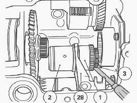
Provisionally fit the set screw (8) in order to hold the selector rail
in place to remove the fork (28). Slide the sleeve (2) and the coupler
(1) closer together on the
connecting shaft (3). Note and mark the assembly order of the sleeve
(2).
Disengage the sleeve/connecting shaft/coupler assembly towards the outer
left-hand side. Take it out of the fork (28) and remove it through the
opening in the
right-hand cover plate. Remove the fork (28) on the selector rail (7).
Remove the lever (3).
To remove the creeper unit control rod (1), turn it so that it passes
beneath the selector rail (7). Discard the "O" ring (3). Clean and check
all components. Replace
those that are defective. Install the control rod and pull it as far to
the right as possible. Fit a new lubricated "O" ring. Install the lever
(3). Tighten the screw.
Install the fork on the selector rail. Ensure that the finger (1) of the
creeper gear control rod is pointing towards the front of the Massey
Ferguson 5430, 5450 tractor.
Couple the sleeve/connecting shaft/coupler assembly inside the housing.
Place it in the fork, turning the machined groove on the sleeve (2)
towards the rear of the tractor. Slide the sleeve and coupler onto the
connecting shaft. Install a
new double pin into the sleeve.
Take out the set screw (8). Install a
new pin (29) and turn the selector rail (7). Clean the set screw (8).
Smear its thread with Loctite
542 and tighten to a torque of 38 - 43 Nm.
Ensure that the ball bearing fitted at the end of the locking screw (27)
returns correctly to its initial position after pressure has been
applied manually by the locking
screw. Position the fork (28) and locking screw on flat section "M" of
the selector rail (7) (between the two locking slots.
Fully tighten the screw without forcing it in order to compress the ball
bearing. Loosen the screw by one-quarter turn. Clean the nut (26) and
smear with Loctite 270
or equivalent. Tighten to a torque of 15 - 20 while holding the locking
screw in place. Check that the fork locks correctly.
Turn and push the rod (2) in order to engage the finger in the fork. Fit
the screw (1) smeared with Loctite 542 or equivalent. Check that the rod
operates correctly.
Check that the "O" rings for the internal hydraulic pipes are not
damaged. Install the right-hand cover plate.
Attach the electrical harnesses with a retainer. Install the trailer
brake valve (if fitted, open centre), checking that the "O" rings are
not damaged. Tighten the screws
to a torque of 25-35 Nm. Reconnect the pipes and hoses via the hydraulic
cover plate. Install the strainer, support and filter (open centre).
If necessary, on 4WD MF 5430, 5450 tractors:
- couple the rear sleeve (5) of the transmission shaft (3);
- Install the guard (1);
- reconnect the front differential lock control hoses.
Install the plugs (1), the springs (2) and the detent plungers (3).
Install the selector cover plate. Reconnect and adjust the creeper unit
control cable.
Install the wheel. Remove the axle stand and the jack. Tighten the wheel
nuts to a torque of 400 - 450 Nm.
Top up the oil level in the rear axle and gearbox. Start the tractor.
Check the correct operation of the electrical and electronic circuits.
Check the tightness of the
cover plate mating face and the hydraulic unions. Carry out a road test
of the creeper unit control and 1st, 2nd, 3rd, 4th gears of the
Hare/Tortoise ranges.
Hare / Tortoise fork and lock- 1st / 2nd - 3rd / 4th fork assembly and
selector rail
Remove the right-hand rear wheel. Chock the Massey Ferguson 5430, 5450
tractor.
Remove the selector cover plate. Remove the right-hand hydraulic cover
plate.
Remove the plugs (1), the springs (2) and the detent plungers (3). The
detent plungers are now longer.
This modification improves their guiding into the forks (5) and (6) and
also into the plugs (1).
To optimise operation, a decompression spring on the detent plunger
drives out the oil enclosed in the spring chamber (2).
This design allows the plunger to enter and exit the fork more smoothly,
thus improving gear shifting. Take out set screw (8).
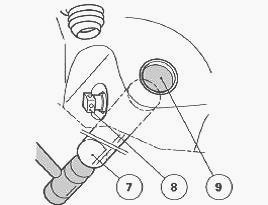
Drive out the cup plug (9) forwards by striking the rear end of the
selector rail (7).
Place the Tortoise and Hare fork (20) in the Hare position. Remove the
adjustment screws (19).
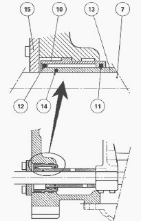
Remove the screws (16) and the cover plate (15). Take out the Hare and
Tortoise piston (13) and discard the seals.
Remove the cylinder (10) and discard the seal. Turn the pump suction
pipe (1) upwards.
Move the selector rail (7) to the rear in order to release the forks.
Slide the selector rail under the rear axle housing reinforcement.
Take out the 1st-2nd and 3rd-4th gear forks. Extract the Hare and
Tortoise fork. If necessary, remove the locking stop (18).
Take the selector rail out through the selector cover plate opening by
passing it through the Hare / Tortoise cylinder bore.
Clean and check all components. Replace those that are defective.
Install the selector rail through the selector cover plate opening and
the Hare / Tortoise cylinder
bore.
Install the forks. Check that the hydraulic ports in the Hare /
Tortoise cylinder (10) are not obstructed. Install the cylinder fitted
with a new "O" ring (11).
The cylinder (10) is held in position:
- at the front, by the shoulder machined on its outer diameter;
- at the rear, by the cover plate (15).
Slide the selector rail forwards into the Hare / Tortoise fork and the
3rd-4th and 1st-2nd forks.
On the piston (13), fit the "O" rings (12) (14), and then insert the
piston into the cylinder bore (10) and onto the selector rail (7).
Turn the adjustment screw holes towards the tapped holes on the fork.
Temporarily lock the piston with a screw (19).
Install the cover plate (15) with the screws (16). Tighten the screws to
a torque of 25-35 Nm.
Clean the set screw (8). Smear its thread with Loctite 542 or
equivalent. Tighten to a torque of 38 - 43 Nm.
Smear the cup plug (9) with Loctite 542 or equivalent. Install it flush
with the housing.
Install the detent plungers, springs and locking plugs. Tighten the
plugs to a torque of 50 - 70 Nm.
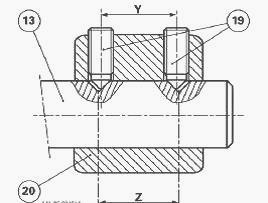
Adjusting the clearance between the Hare / Tortoise fork pads and the
synchroniser sliding coupler
The positioning of fork (20) is obtained by adjusting the difference in
the dimension between the centre line of the tapped holes "Y" and the
centre line of the indents
"Z" on the piston (13). A different fork movement is obtained either by
adjusting the front screw or by adjusting the rear screw according to
the adjustment required.
Position the control piston (13) and the sliding coupler "C" in the high
range (Hare).
Hold the sliding coupler manually against gear "L" of the high range.
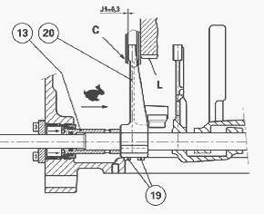
Adjust the position of the fork (20) using the two adjustment screws
(19) previously cleaned in solvent and lightly smeared with Loctite 221
or equivalent, in order to
obtain a clearance of J1 = 0.3 mm between the rear face of the pad and
the sliding coupler.
For this adjustment, use the makeshift tool.
Position the control piston
(13) and the sliding coupler "C" in the low range (Tortoise).
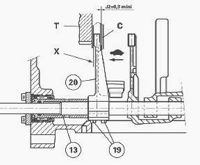
Check that there is a clearance of J2 = 0.3 minimum (this value is
determined by the clearance J1) between the pad and the sliding coupler
when the latter rests
against the gear "T" of the low range.
Alternatively and progressively tighten the screws (19) to a torque of
25 - 35 Nm taking care not to modify the adjustment. In the Tortoise
position, if face "X" of the
fork pad (20) is driven against the sliding coupler "C", increase the
clearance J1. Check that the fork operates correctly.
Adjusting the Hare / Tortoise fork locking stop
Locking is adjusted by an adjustable stop (18) located on the Hare /
Tortoise fork. This adjustment is obtained using a tool whose role
consists of conveying to the
locking stop the positioning of the indexing rod, mounted on the
selector cover plate.
The aim of this adjustment is to make the Hare/Tortoise mechanism safe
during operation, by mechanically locking the fork in the Hare or
Tortoise position. Before
adjusting the locking stop (18), it is essential to adjust the clearance
between the Hare/Tortoise fork pads and the synchroniser sliding
coupler.
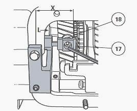
On the cover plate
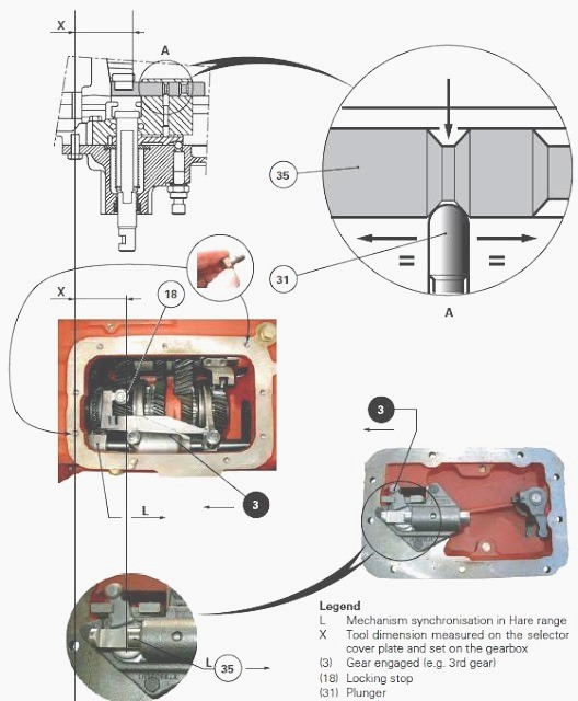
L - Mechanism synchronisation in Hare range, X - Tool dimension measured
on the selector cover plate and set on the gearbox, (3) Gear engaged
(e.g. 3rd gear),
(18) Locking stop, (31) Plunger, (35) Indexing rod
Place the indexing rod (35) in the high range position (Hare). Engage
the 3rd gear ratio. Install the tool on the selector cover plate. It is
essential to equally distribute
the clearance between the indexing rod and the plunger (31) (detail A).
Using the tool, measure dimension X according to pics.
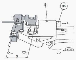
On the MF 5430, 5450 gearbox
Engage the 3rd ratio. Using the tool, set dimension X on the gearbox.
Apply manual pressure on the fork towards the Hare range. Adjust the
locking stop (18) by
placing it in contact with the tool. Lightly smear the thread of the
screw (17) with Loctite 242 or equivalent. Tighten to a torque of 40-50
Nm.
Check
Check the operation of the Hare and Tortoise ranges. Check the smooth
operation of all gears.
Install the right-hand hydraulic cover plate. Install the selector cover
plate.
Reconnect and adjust the creeper unit control (if fitted). Install the
rear wheel.
Tighten the nuts to a torque of 400 - 450 Nm.
Top up the oil level in the housings. Check it using the gauge at the
rear of the centre housing.
Carry out a road test:
- of gears from 1st to 4th and vice versa;
- of the Hare and Tortoise ranges;
- of the creeper unit (if fitted).
Check the tightness of the cover plate mating faces and the hydraulic
unions.
________________________________________________________________________________
________________________________________________________________________________________
 SPECS
SPECS LOADERS
 MAINTENANCE
 PROBLEMS
________________________________________________________________________________________
 MF 1523
 MF 1531
 MF 135
 MF 1547
 MF 1635
________________________________________________________________________________________
________________________________________________________________________________________
 231
231 231S
231S 235
235 240
240 241
241________________________________________________________________________________________
 255
255 265
265 274
274 285
285 375
375________________________________________________________________________________________
________________________________________________________________________________________
 916X Loader
 921X Loader
 926X Loader
 931X Loader
 936X Loader
________________________________________________________________________________________
 941X Loader
 946X Loader
 951X Loader
 956X Loader
 988 Loader
________________________________________________________________________________________
 1655
1655 GS1705
 1742
1742 2635
2635 4608
4608________________________________________________________________________________________
 1080
1080 1100
1100 2615
2615 3050
3050 3060
3060________________________________________________________________________________________
 4708
4708 5455
5455 5450
5450 5610
5610 5613
5613________________________________________________________________________________________
 DL95 Loader
 DL100 Loader
 DL120 Loader
 DL125 Loader
 DL130 Loader
________________________________________________________________________________________
 DL135 Loader
 DL250 Loader
 DL260 Loader
 L90 Loader
 L100 Loader
________________________________________________________________________________________
 6499
6499 7480
7480 7618
7618 7726
7726 1533
1533________________________________________________________________________________________
 2604H
2604H 2607H
2607H 4455
4455 4610M
4610M 4710
4710________________________________________________________________________________________
 L105E Loader
 L210 Loader
 1014 Loader
 1016 Loader
 1462 Loader
________________________________________________________________________________________
 1525 Loader
 1530 Loader
 232 Loader
 838 Loader
 848 Loader
________________________________________________________________________________________
 5712SL
 6713
6713 6715S
6715S 7475
7475 7615
7615________________________________________________________________________________________
 7716
7716 7724
7724 8240
8240 8650
8650 8732
8732________________________________________________________________________________________
 246 Loader
 1036 Loader
 1038 Loader
 1080 Loader
 856 Loader