
________________________________________________________________________________
Massey Ferguson 5425, 5465 hydraulic system - Low flow rate
The Massey Ferguson 5425, 5465 low flow rate
system supplies:
- the steering spool valve;
- the Power Shuttle,
- the Speedshift and its control or the Dyna-4 transmission;
- the Power Shuttle hydraulic control unit;
- the Hare / Tortoise mechanism located at the rear right-hand side of
the gearbox (Speedshift only);
- the 4WD unit located in the lower part of the centre housing;
- the front and rear differential locks;
- the PTO clutch located at the front of the centre housing;
- the PTO brake located in the top cover plate at the back of the centre
housing.
An additional function ensures the lubrication of mechanical components
and maintains the level in the brake master cylinders (except Meritor).
Checking the flow rate of the pump
When carrying out tests, the rear axle must not be placed on chocks with
the MF 5425, 5465 front axle (4WD) engaged.
Connect a flowmeter between the 15 micron filter(s) outlet located to
the front right-hand side of the rear axle, and the supply hose to the
Orbitrol spool valve. Check
that the flowmeter load valve remains fully open throughout the test.
Also connect a pressure gauge to the low pressure diagnostics connector
screwed to the top of the right-hand hydraulic cover plate, at the
front. Check Q3.
Engine speed (rpm) P4 (bar) Q3 (l/min) Correct position
1000 18 ±1 16.0± 1 steering at neutral
2200 18 ±1 32.7± 2 steering at neutral
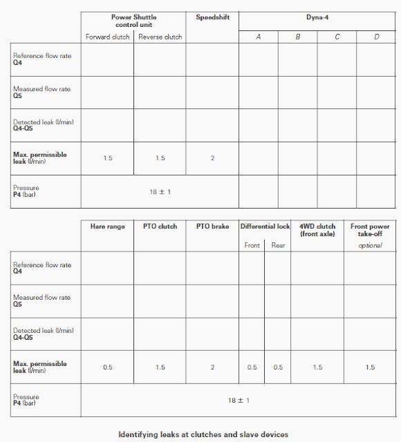
Checking for leaks at clutches and slave devices
To adjust reference flow rate Q4:
- all low pressure functions should be at neutral;
- the front axle should be engaged (clutch not supplied, indicator light
on);
- the range lever should be in Tortoise position (icon);
- the reverse shuttle control should be in neutral position;
- Speedshift version:
- Speedshift should be in D range;
Massey Ferguson 5425, 5465 Dyna-4 transmission:
- The Dyna-4 should be in C range;
- The differential lock should be disengaged (indicator light off),
- the power take-off should be disengaged (indicator light off).
The flowmeter can be connected:
- either to the cooler outlet;
- or where the pipe joins the hose on the right-hand side of the MF
5425, 5465 tractor.
- The flowmeter should be connected using makeshift unions.
- Connect the flowmeter as required (see previous remark).
- Connect a pressure gauge set to approximately 30 bar to the low
pressure connector (1).
- Note the Q4 reference flow rate at 1000 rpm.
- Activate each function separately and note the Q5 flow rate.
- The difference Q4 - Q5 represents the leak detected.
Conclusion: Leak exceeds permissible value
Before checking the following function and to avoid misreading the Q5
flow rate, bring the control of the component tested back to the neutral
position or to the above
neutral positions.
When all Massey Ferguson 5425, 5465 tractor clutch
and slave devices are activated, the low pressure P4 should remain at 18
± 1 bar.
The leaks in the single control systems can be detected according to the
values in the table. For the differential lock function, an additional
test is necessary to
determine the difference between the front and rear.
Checking method - Disconnect and block one of the piston supplies. Check
if the leak is still present.
Supply to the steering spool valve
Connect a pressure gauge fitted with a coupler, to the diagnostics
connector of the right-hand hydraulic cover plate.
Turn the steering to full lock and check that: P5 = 170 bar at 1000 rpm
and at 2200 rpm.
Supply to the MF 5425, 5465 tractor steering ram
Connect a pressure gauge bypass to each hose of the steering ram.
With steering at neutral, check that P6 = 18 bar. Turn the steering
wheel.
Pressure P6 should be: between 18 and 170 bar at the ram supply side; 18
bar in the return line.
Checking for leaks in the steering system
Run the engine at 1000 rpm. Turn the steering on full lock and apply a
torque of 4 Nm to the steering column.
The steering wheel must not turn
more than 2 rpm.
If the steering wheel turns more than 2 rpm, disconnect the pipes that
supply the rams, block the two ports and then apply the same torque (4
Nm) to the steering
wheel.
If it turns at less than 2 rpm, there is a leak at the ram.
Checking the supply pressure of the Power Shuttle control unit
Connect a pressure gauge with a capacity of approximately 30 bar to the
diagnostics connector of the control unit located at the front right of
the gearbox. Check P7.
Engine speed (rpm) P7 (bar)
1000 18 ± 1
2200 18 ± 1
Checking the pressure of the Power Shuttle F/R clutches
Speedshift version
To keep the tractor stationary, ensure that the transmission lever is in
neutral. The diagnostics connectors forward) and reverseof the Power
Shuttle clutches are on
the control unit fitted to the front right of the gearbox.
The Power Shuttle control lever is located to the left beneath the
steering wheel:
- lever in upward position: forward travel (the letter F is displayed on
the instrument panel);
- lever in downward position: reverse travel (the letter R is displayed
on the instrument panel).
- Connect a pressure gauge with a capacity of approximately 30 bar to
each diagnostics connector.
- Run the engine at 1000 rpm.
- Activate the lever to select the direction (forward / reverse) and the
neutral position.
- Check P8 and P9.
Lever position Forward clutch (1) P8 (bar) Reverse clutch (2) P9 (bar)
Forward 18 ± 1 0
Neutral or de-clutched 0 0
Reverse 0 18 ± 1
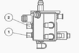
Massey Ferguson 5425, 5465 Dyna-4 transmission version
The diagnostics connectors forward and reverse of the shuttle clutches
are on the control unit fitted to the front right of the gearbox as
shown in figure. The Power
Shuttle control lever is located to the left beneath the steering wheel:
lever in upward position - forward travel, lever in downward position -
reverse travel.
Connect a pressure gauge with a capacity of approximately 30 bar to each
diagnostics connector (1) and (2).
Run the engine at 1000 rpm.
Activate the lever to select the direction (forward / reverse) and the
neutral position.
Check P8 and P9.
Lever position Forward clutch (1) P8 (bar) GTA2520 Reverse clutch (2) P9
(bar) GTA2520
Forward 20 ± 1 0
Neutral or de-clutched 0 0
Reverse 0 20 ± 1
Checking the lubrication pressure of the MF 5425, 5465 Power Shuttle F/R
clutches (Speedshift version only)
- These clutches are lubricated by a gear pump that is independent from
that used for the standard lubrication system.
- This pump has two additional spools which act as valves and are fitted
in the front cover plate of the Power Shuttle. They thus lubricate the
reverse position.
- The check is carried out with the assistance of an operator positioned
in the operator's seat.
- Connect a pressure gauge with a capacity of approximately 11 bar to
the diagnostics connector located at the front right of the gearbox.
- Check P10 as indicated in the table.
Lever position Engine speed (rpm) P10 (bar) Pedal engaged Pedal
disengaged
Forward ratio (letter F) 1000 0.5 ± 0.1 1.5 ± 0.1
2200 0.9 ± 0.1 2.0 ± 0.1
Neutral 1000 1.5 ± 0.1 1.5 ± 0.1
2200 2.0 ± 0.1 2.0 ± 0.1
Reverse ratio (letter R) 1000 0.4 ± 0.1 1.5 ± 0.1
2200 0.8 ± 0.1 2.0 ± 0.1
Checking the pressure on the Speedshift supply line
Run the engine at 1000 rpm.
Connect a pressure gauge with a capacity of approximately 30 bar to the low pressure diagnostics connector screwed into the upper part of the right-hand hydraulic cover plate.
Measure the pressure: P4 =
18 bar ± 1 bar
Checking the dry clutch pressure (Speedshift version only)
The pressure can reach 30 bar when the pedal is pressed down; it is
therefore necessary to connect the pressure gauge after starting the
engine.
Connect a pressure gauge with a capacity of 30 bar fitted with a coupler
to the diagnostics connector located on the right-hand side of the
gearbox.
Run the engine at 1000 rpm. Measure the pressure:
P8 = 1.5 bar maximum clutch engaged
P8 = 13-15 bar clutch disengaged: new disc
P8 = 18-20 bar clutch disengaged: worn disc
________________________________________________________________________________
________________________________________________________________________________________
 SPECS
SPECS LOADERS
 MAINTENANCE
 PROBLEMS
________________________________________________________________________________________
 MF 1523
 MF 1531
 MF 135
 MF 1547
 MF 1635
________________________________________________________________________________________
________________________________________________________________________________________
 231
231 231S
231S 235
235 240
240 241
241________________________________________________________________________________________
 255
255 265
265 274
274 285
285 375
375________________________________________________________________________________________
________________________________________________________________________________________
 916X Loader
 921X Loader
 926X Loader
 931X Loader
 936X Loader
________________________________________________________________________________________
 941X Loader
 946X Loader
 951X Loader
 956X Loader
 988 Loader
________________________________________________________________________________________
 1655
1655 GS1705
 1742
1742 2635
2635 4608
4608________________________________________________________________________________________
 1080
1080 1100
1100 2615
2615 3050
3050 3060
3060________________________________________________________________________________________
 4708
4708 5455
5455 5450
5450 5610
5610 5613
5613________________________________________________________________________________________
 DL95 Loader
 DL100 Loader
 DL120 Loader
 DL125 Loader
 DL130 Loader
________________________________________________________________________________________
 DL135 Loader
 DL250 Loader
 DL260 Loader
 L90 Loader
 L100 Loader
________________________________________________________________________________________
 6499
6499 7480
7480 7618
7618 7726
7726 1533
1533________________________________________________________________________________________
 2604H
2604H 2607H
2607H 4455
4455 4610M
4610M 4710
4710________________________________________________________________________________________
 L105E Loader
 L210 Loader
 1014 Loader
 1016 Loader
 1462 Loader
________________________________________________________________________________________
 1525 Loader
 1530 Loader
 232 Loader
 838 Loader
 848 Loader
________________________________________________________________________________________
 5712SL
 6713
6713 6715S
6715S 7475
7475 7615
7615________________________________________________________________________________________
 7716
7716 7724
7724 8240
8240 8650
8650 8732
8732________________________________________________________________________________________
 246 Loader
 1036 Loader
 1038 Loader
 1080 Loader
 856 Loader