
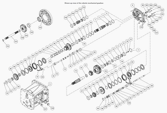
________________________________________________________________________________
MF 5460, 5470 Robotic mechanical gearbox - Primary and secondary shafts
Disassembling the primary shaft
The bearing cones (2) and (50) are fitted tight on the shaft.
Position the shaft on a work surface with a suitable supporting fixture
to hold the shaft in a vertical position.
Take off the ring (53) at the end of the shaft (Massey Ferguson 5460,
5470 rear axle end).
Install a shouldered washer at the end of the shaft (1) in order to
Install an extractor.
Using the extractor, pull the pinion (48) and remove the bearing (50)
and the pinion (48). Recover the lubricating bush (49).
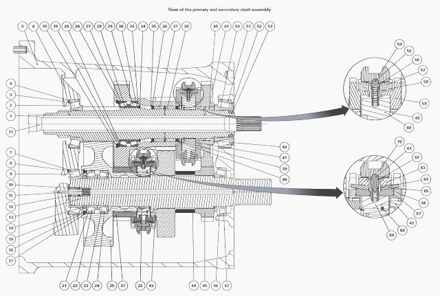
Remove the synchroniser assembly (60). Remove the circlip (42).
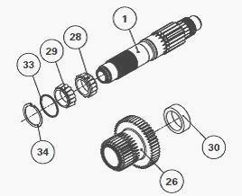
Take off the circlip (18) to remove the double pinion (26). The bearings
(37) and (38) stay in the double pinion (26).
The bearing cones (28) and (29) stay on the shaft (1). Recover the
washer (19) and the shims (20).
Remove the bearing cup (30) from the pinion (26). Check whether or not
there is a shim behind the cup.
Remove the snap ring (40). Take off the needle bearings (38) and (37)
with the spacers (36) and (39). Remove the snap ring (35) if required.
Remove the circlip (34), washer (33) and bearing cones (28) and (29). If
necessary, remove the bearing cone (2).
Reassembling the primary shaft
Pair up the cones (28)(29) and cups (27)(30). Install the bearing cones
(28) and (29) on the shaft (1).
Next install the washer (33) and circlip (34). It is assembled as an X.
The cones are placed back to back.
Install the cup (30) in the double
pinion (26). Check the
presence of the snap ring (35) in the double pinion.
Install the spacer (36), greased needle bearings (37) and (38), and
spacer (39) in the pinion (26). Install the snap ring (40).
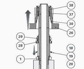
Slide the shaft (1) into the pinion (26). Install the washer (19) and
circlip (18). Do not insert shims to measure the clearance during this
operation.
Shimming the pinion
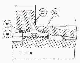
In order to position the bearings correctly, push and pull the pinion
(26) while turning it.
Place a dial gauge feeler pin on the surface of the pinion (26). Measure
the clearance A at three points.
Calculate the average of the three readings. Remove the circlip (18) and
the washer (19).
Between the cup (27) and washer (19) insert the thickness of shims
required to obtain clearance A: A = -0.05 to 0.05 mm.
Shim to the maximum tolerance (low preload).
Shimming the synchroniser overlap
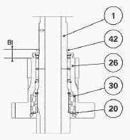
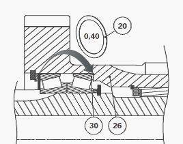
Install the thickness of shims. Install the circlip (42) holding the
synchroniser in position (60).
Using a depth gauge, measure distance B between the mating face of the
synchroniser (60) on the circlip (42) and the mating face of the pinion
(26).
Ensure distance B does not exceed 16.33 mm:
- If B<16.33: the dimensions are correct.
- If B>16.33: take out one 0.40 mm shim (20) used to shim the pinion
(26), and place it between the pinion (26) and the cup (30).
There are no intermediate shim sizes; use either the 0.40 mm shim or no
shim.
Once the shimming is complete, refit the synchronizer (60).
Make a paint mark to correctly align the lubricating ports on the
synchroniser hub and the shaft (1).
Reinstall the bush (49) and pinion
(48). Using a makeshift tool, fit
the bearing cones (2) and (50) on the shaft (1).
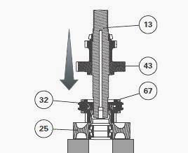
Disassembling the secondary shaft
Take care not to pull the pinion (25) or the synchroniser will come
apart. The bearing cone (9) is freely mounted on the shaft (1).
Remove the bearing cone (9) and the spacer (14). Install the shaft
vertically on the pinion (25).
Pull the shaft (13) upwards with the pinions (43) and (45), taking care
not to disassemble the synchronizer (69).
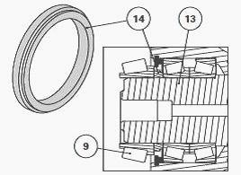
Recover the needle bearing (32). Extract the snap ring (68). Remove the
synchronizer (69) and pinion (31). Turn over the pinion (25).
Take off the circlip (15), washer (16) and shims (17). Remove and pair
up the bearings (21)(22) and (23)(24).
Using an extractor, pull the pinion (45) and remove the bearing (46).
Remove the spacer (44) and pinion (43).
Reassembling the secondary shaft
On the shaft (13), Install: pinion (43), spacer (44), pinion (45).
Install the bearing cone (46) using a makeshift tool.
In the pinion (25), fit the roller bearings (21)(22) and (23)(24).
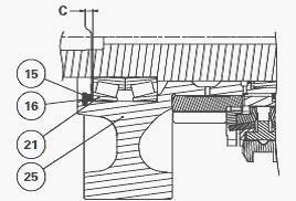
Install the washer (16) then the circlip (15). Do not fit shims (17).
Using a set of shims, measure the clearance C between the circlip (15)
and the washer (16).
Between the bearing (21) and washer (16) insert the thickness of shims
(17) required to obtain clearance C: C = -0.05 to 0.05 mm.
Shim to the maximum tolerance (low preload).
On the pinion (25), reinstall the pinion (31), its inner surface lightly
greased.
Reassemble the synchroniser (69) on the splines of the pinion (25).
Make a paint mark to correctly align the lubricating ports on the
synchroniser hub and the pinion (25).
Install the snap ring (68). Install the pre-greased bearing (32).
Position the pinion (25) on a support, with the synchroniser turned
upwards.
Thread on the shaft (13) assembled during, paying special attention when
inserting it through the needle bearing (32).
Install the spacer (14) and bearing cone (9) on the shaft (13). Ensure
the spacer shoulder is positioned the right way.
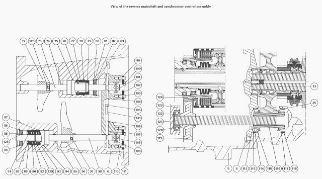
Shimming the primary shaft and reverse transfer pinion
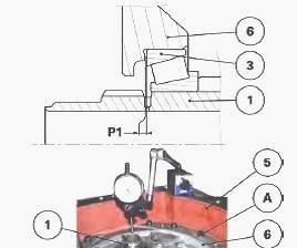
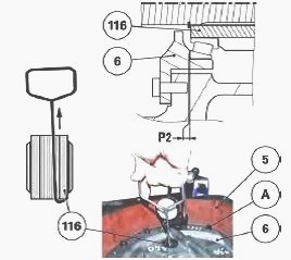
Check the presence of the bearing cups (51), (47) and (118) in the
Massey Ferguson 5460, 5470 gearbox housing (5).
In the gearbox housing (5), position the primary shaft (1) assembled
during operations.
At the same time, Install the reverse transfer pinion
(116).
In the cover (6), Install the bearing cups (3) and (114) (assembled
without shims) with grease to keep them in the cover (6).
Reinstall the cover (6) on the housing (5). Install and tighten the cover screws (A). Place a dial gauge feeler pin at the end of the primary shaft (1).
In order to correctly seat the bearings, pull and push hard on the shaft
while turning it. To pull the shaft, use a lever positioned underneath
the gearbox.
Measure the clearance with a dial gauge. Calculate the thickness of
shims required to obtain preload P1: P1 = 0.05 to 0.10 mm.
Example if the clearance measured is 0.73: 0.73 + 0.05 = 0.78/ 0.73 +
0.10 = 0.83.
The thickness of shims required will be between 0.78 and 0.83. Get as
close as possible to 0.83.
Place the dial gauge feeler pin on the reverse transfer pinion.
Using a makeshift bent rod, pull the pinion to correctly seat the
bearings.
Measure the clearance with a dial gauge. Calculate the thickness of
shims required to obtain preload P2: P2 = 0.05 to 0.10 mm.
Remove the screws (A) and the cover (6). Take out the primary shaft and
reverse transfer pinion.
Shimming the secondary shaft
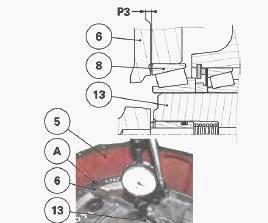
Check the presence of the bearing cup (47) in the MF 5460, 5470 gearbox
housing (5).
In the gearbox housing (5), position the secondary shaft (13) assembled
during operations.
In the cover (6), Install the bearing cups (8) (assembled without shims)
with grease to keep them in the cover (6).
Reinstall the cover (6) on the housing (5). Install and tighten the
cover screws (A).
Place a dial gauge feeler pin at the end of the secondary shaft (13).
In order to correctly seat the bearings, pull and push hard on the shaft
while turning it.
To pull the shaft, use a lever positioned underneath the gearbox.
Measure the clearance with a dial gauge. Calculate the thickness of
shims required to obtain preload P3: P3 = 0.05 to 0.15 mm.
If possible, shim to obtain maximum tolerance. Reinstall the shafts in the housing and fit the cover with the calculated shim thicknesses.
________________________________________________________________________________
________________________________________________________________________________________
 SPECS
SPECS LOADERS
 MAINTENANCE
 PROBLEMS
________________________________________________________________________________________
 MF 1523
 MF 1531
 MF 135
 MF 1547
 MF 1635
________________________________________________________________________________________
________________________________________________________________________________________
 231
231 231S
231S 235
235 240
240 241
241________________________________________________________________________________________
 255
255 265
265 274
274 285
285 375
375________________________________________________________________________________________
________________________________________________________________________________________
 916X Loader
 921X Loader
 926X Loader
 931X Loader
 936X Loader
________________________________________________________________________________________
 941X Loader
 946X Loader
 951X Loader
 956X Loader
 988 Loader
________________________________________________________________________________________
 1655
1655 GS1705
 1742
1742 2635
2635 4608
4608________________________________________________________________________________________
 1080
1080 1100
1100 2615
2615 3050
3050 3060
3060________________________________________________________________________________________
 4708
4708 5455
5455 5450
5450 5610
5610 5613
5613________________________________________________________________________________________
 DL95 Loader
 DL100 Loader
 DL120 Loader
 DL125 Loader
 DL130 Loader
________________________________________________________________________________________
 DL135 Loader
 DL250 Loader
 DL260 Loader
 L90 Loader
 L100 Loader
________________________________________________________________________________________
 6499
6499 7480
7480 7618
7618 7726
7726 1533
1533________________________________________________________________________________________
 2604H
2604H 2607H
2607H 4455
4455 4610M
4610M 4710
4710________________________________________________________________________________________
 L105E Loader
 L210 Loader
 1014 Loader
 1016 Loader
 1462 Loader
________________________________________________________________________________________
 1525 Loader
 1530 Loader
 232 Loader
 838 Loader
 848 Loader
________________________________________________________________________________________
 5712SL
 6713
6713 6715S
6715S 7475
7475 7615
7615________________________________________________________________________________________
 7716
7716 7724
7724 8240
8240 8650
8650 8732
8732________________________________________________________________________________________
 246 Loader
 1036 Loader
 1038 Loader
 1080 Loader
 856 Loader