
________________________________________________________________________________
Massey Ferguson 5465, 5475 robotic mechanical gearbox - Selector rails and forks
To carry out this adjustment, the primary and secondary shafts must be
correctly supported and shimmed in the housing.
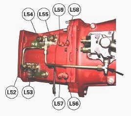
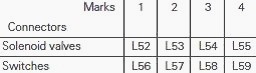
(L52) Range 1 control solenoid valve, (L53) Range 2 control solenoid
valve, (L54) Range 3 control solenoid valve, (L55) Range 4 control
solenoid valve, (L56) Range 1 switch, (L57) Range 2 switch, (L58) Range
3 switch, (L59) Range 4 switch
Install solenoid valves (L52), (L53), (L54) and (L55). Fashion a union
to supply the control circuit with compressed air at a maximum pressure
of 4 bar. Connect the selector rail adjustment tool.
The selector rail adjustment tool is used to supply the solenoid valves
(L52), (L53), (L54) and (L55) of the gearbox, in order to carry out
various adjustments.
The range switches (L56), (L57), (L58) and (L59) can be checked once the
selector rails have been adjusted and the switches fitted. Each LED on
the tool corresponds to a switch.
The switches on the tool supply the solenoid valves of the Massey
Ferguson 5465, 5475 tractor gearbox. They work independently of the LED
lighting. The range switches light the LEDs of the tool. When a range is
engaged, the corresponding LED for the range is lit.
The switches are normally closed. When a range is engaged, they open the
circuit and the implement reverses the signal to light the LEDs. When
the switches are not connected, the four LEDs on the tool are thus lit.
Connect the tool to a 12V, 4A power supply.
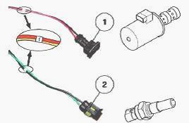
Connect the connectors (1) to the solenoid valves and the connectors (2)
to the range switches.
Each wire is marked with a number indicating the range concerned.
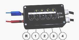
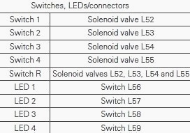
Switches, LEDs/connectors
Switch 1 - Solenoid valve L52, Switch 2 - Solenoid valve L53, Switch 3 -
Solenoid valve L54, Switch 4 - Solenoid valve L55, Switch R - Solenoid
valves L52, L53, L54 and L55, LED 1 - Switch L56, LED 2 - Switch L57,
LED 3 - Switch L58, LED 4 - Switch L59
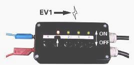
Supplying the MF 5465, 5475 tractor gearbox solenoid valves Activate
switches 1, 2, 3 and 4 one by one, in order to supply the solenoid
valves required to adjust the selector rails. To return the two selector
rails to neutral automatically, use switch R on the implement (4
solenoid valves supplied).
Checking the selector rails before
adjustment
Before adjusting the travel of the selector rails, it is important to
check that their movement is within the permitted tolerances.
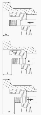
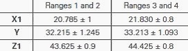
Using a depth gauge and a suitable fixture, check the following
dimensions (see the table):
- X1: distance between face F of the housing and the end of the selector
rail with the range 1 or 3 engaged,
- Y : distance between face F of the housing and the end of the selector
rail in neutral position,
- Z1: distance between face F of the housing and the end of the selector
rail with the range 2 or 4 engaged.
X1 20.785 ± 1 21.830 ± 0.8
Y 32.215 ± 1.245 33.213 ± 1.093
Z1 43.625 ± 0.9 44.425 ± 0.8
If the measured dimensions are outside these tolerances, manually turn
the gears using the reverse driving pinion, then repeat the
measurements. If the dimensions
are still incorrect, check that the selector rails and synchronisers
have been fitted correctly.
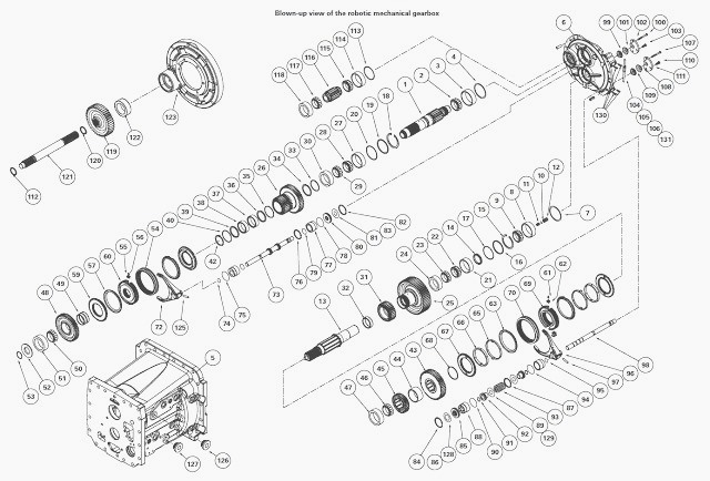
Adjusting the selector rails
Set the rail (98) to neutral. Install the castellated nut without
tightening (109).
Engage range 2. (Supply L53). Tighten the nut (109) up against the cover
(6). Reposition the selector rail to neutral.
Screw on the nut (109) by two slots and line up the next slot opposite
the hole of the locking screw (107).
With paint, mark the position of the nut (109) in relation to the cover
(6).
The synchroniser may not fully engage when the MF 5465, 5475 gearbox is
not running.
If this is the case, position the shaft (121) and reverse transfer
pinion (119) and slowly run the gearbox while engaging the range.
Install the castellated nut (108). Screw it on until it is almost
touching the nut (109).
Ensure the nut (109) stays in its set position and that the paint marks
are not removed.
Install the plate (111). Install the screws (110) smeared with Loctite
242 or equivalent. Tighten to a torque of 29 - 37 Nm.
Engage range 1. (Supply L52). Unscrew the nut (108) fitted home against
the cover (111).
Reposition the selector rail to neutral.
Unscrew the nut (108) by two
slots and line up the next slot opposite the hole of the locking screw
(107).
With paint, mark the nut (108) aligned with the mark on the cover (6).
Insert the screw (107) to lock the nuts (108) and (109), aligning the
marks made during operations.
Check for correct operation. The nuts should effectively act as a stop.
Firmly fit the screw (107), lightly smeared with Loctite 242 or
equivalent. Tighten to a torque of 12 - 16 Nm.
Adjusting selector rail (73) (ranges 3 and 4). Repeat operations with
the selector rail (73) and nuts (99) and (101).
Adjusting the interlock mechanism
This adjustment must be carried out after setting the MF 5465, 5475
tractor gearbox selector rails.
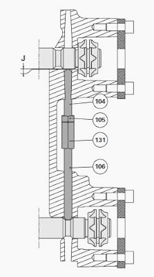
Screw home the rod (106) in the reverse pitch nut (131).
Using the selector rail adjustment tool, engage a range on a selector
rail and leave the other selector rail in neutral.
Unscrew the rod (104) until the lock reaches maximum axial clearance as
shown in: J = 0.1 to 0.3 mm. Tighten the locknut (105).
Check - Using the selector rail adjustment tool, engage a range on a
selector rail. Try to shift a range on the other selector rail. It
should not engage. Repeat the
procedure with all the ranges.
Assembling the intermediate speed sensor
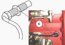
Install the sensor (C) lightly smeared with Loctite 577 or equivalent.
Screw the sensor home on the pinion (25) without forcing it, then
unscrew of a turn. Tighten the locknut to a torque of 5 - 7 Nm.
Install the gearbox on the rear axle and engine. Reconnect the harnesses
and hydraulic pipes that were removed.
Check the level of the transmission oil. Carry out a gearbox calibration and check the transmission for correct operation.
________________________________________________________________________________
________________________________________________________________________________________
 SPECS
SPECS LOADERS
 MAINTENANCE
 PROBLEMS
________________________________________________________________________________________
 MF 1523
 MF 1531
 MF 135
 MF 1547
 MF 1635
________________________________________________________________________________________
________________________________________________________________________________________
 231
231 231S
231S 235
235 240
240 241
241________________________________________________________________________________________
 255
255 265
265 274
274 285
285 375
375________________________________________________________________________________________
________________________________________________________________________________________
 916X Loader
 921X Loader
 926X Loader
 931X Loader
 936X Loader
________________________________________________________________________________________
 941X Loader
 946X Loader
 951X Loader
 956X Loader
 988 Loader
________________________________________________________________________________________
 1655
1655 GS1705
 1742
1742 2635
2635 4608
4608________________________________________________________________________________________
 1080
1080 1100
1100 2615
2615 3050
3050 3060
3060________________________________________________________________________________________
 4708
4708 5455
5455 5450
5450 5610
5610 5613
5613________________________________________________________________________________________
 DL95 Loader
 DL100 Loader
 DL120 Loader
 DL125 Loader
 DL130 Loader
________________________________________________________________________________________
 DL135 Loader
 DL250 Loader
 DL260 Loader
 L90 Loader
 L100 Loader
________________________________________________________________________________________
 6499
6499 7480
7480 7618
7618 7726
7726 1533
1533________________________________________________________________________________________
 2604H
2604H 2607H
2607H 4455
4455 4610M
4610M 4710
4710________________________________________________________________________________________
 L105E Loader
 L210 Loader
 1014 Loader
 1016 Loader
 1462 Loader
________________________________________________________________________________________
 1525 Loader
 1530 Loader
 232 Loader
 838 Loader
 848 Loader
________________________________________________________________________________________
 5712SL
 6713
6713 6715S
6715S 7475
7475 7615
7615________________________________________________________________________________________
 7716
7716 7724
7724 8240
8240 8650
8650 8732
8732________________________________________________________________________________________
 246 Loader
 1036 Loader
 1038 Loader
 1080 Loader
 856 Loader