________________________________________________________________________________
Massey Ferguson 5610, 5612 Dyna 6 Transmission - Power Shuttle
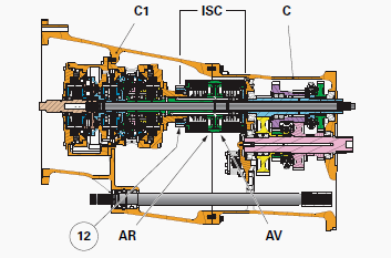
The Power Shuttle is fitted to Massey Ferguson 5610, 5612 tractors equipped with a GBA15 robotic mechanical gearbox.
It is located between front housing C1 of the Powershift module and
housing C of the robotic gearbox. It acts as the main clutch for the
Dyna-6 transmission.
The MF 5610, 5612 Power Shuttle Dyna 6 comprises two
electrohydraulically controlled multidisc clutches: the front multidisc
clutch for forward travel / the rear multidisc clutch for reverse
travel.
This comprises:
- a bell housing;
- a hydraulic piston fitted with Quadring seals;
- a set of ten Belleville washers;
- a hub splined to the primary shaft of the robotic gearbox;
- a set of nine discs and nine intermediate plates;
- a cover plate.
It comprises the same hydraulic and mechanical components as the front
clutch with the exception that, for the rear clutch, the hub forms a
unit with the reverse
driving gear (12). The Power Shuttle multidisc clutches are fitted back
to back. Their clutch bell housing is driven by a common shaft.
The Massey Ferguson 5610, 5612 tractor multidisc clutches are supported:
- at the front by a support fixed to the rear of the Dynashift module;
- at the rear by the robotic gearbox primary shaft.
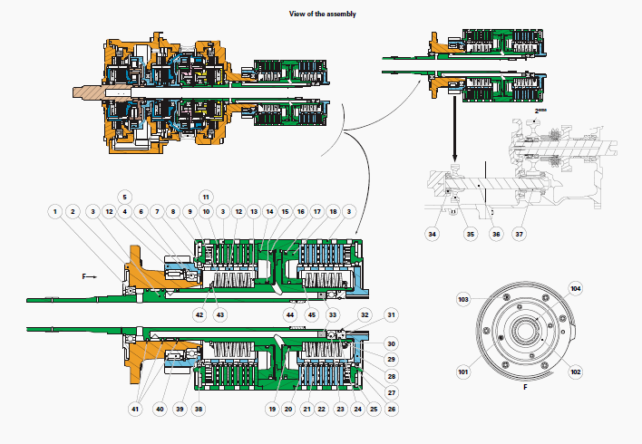
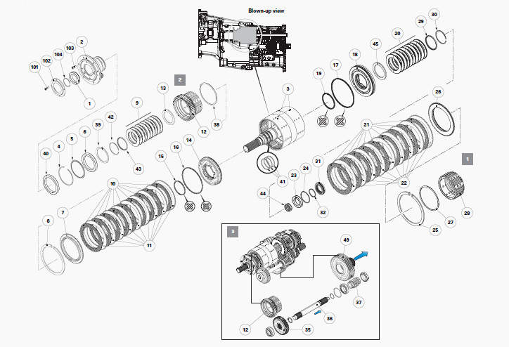
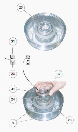
Parts list
(1) Ball bearing sealed on one face, (2) Bearing carrier, (3) Shaft/bell
housings, (4) Circlip, (5) Thrust washer, (6) Ball bearing, (7) Cover
plate (reverse clutch), (8)
Circlip, (9) Belleville washers, (10) Discs (reverse clutch), (11)
Intermediate plates (reverse clutch), (12) Hub/reverse driving gear
unit, (13) Thrust washer, (14)
Piston (reverse clutch), (15) Quadring seal, (16) Quadring seal, (17)
Quadring seal, (18) Piston (forward clutch), (19) Quadring seal, (20)
Belleville washers, (21)
Discs (forward clutch), (22) Intermediate plates (forward clutch), (23)
Ball bearing, (24) Seal ring, (25) Circlip, (26) Cover plate (forward
clutch), (27) Snap ring, (28)
Hub (forward clutch), (29) Countersunk thrust washer, (30) Snap ring,
(31) Seal holder, (32) "O" ring, (33) Rivets, (34) Ball bearing, (35)
Reverse driven gear, (36)
Reverse layshaft, (37) Reverse layshaft gear, (38) Snap ring, (39)
Circlip, (40) Cylindrical roller bearing, (41) Seal rings, (42) Snap
ring, (43) Countersunk thrust
washer, (44) Needle roller bearing, (45) Thrust washer, (49) 2nd gear
(robotic mechanical gearbox), (101) M6 screw, (102) Thrust plate, (103)
M8 screw, (104)
Snap ring, 1 - Forward clutch, 2 - Reverse clutch, 3 - Reverse
kinematics
Removing and refitting the front support and the Power Shuttle multidisc
clutches
If the operation is limited solely to the removal of one or more of the
following parts of the forward clutch:
- discs (21);
- intermediate plates (22);
- hub (28);
- seal holder (31);
- ball bearing (23),
Simply disassemble the MF 5610, 5612 tractor between housing of the
robotic gearbox (C) and housing of the Powershift module (C1).
If it is necessary to completely remove the PowerShuttle, proceed as
follows:
- Disconnect the Massey Ferguson 5612, 5610 tractor between housing C of
the robotic gearbox and housing C1 of the Powershift module.
- Separate housing C1 from the engine. Remove the Powershift module.
- Open the Powershift module between the housing and the rear cover
plate of the Dynashift module.
- Remove clutch O/brake N from the Dynashift module.
- Place the Power Shuttle in a vertical position on a suitable support.
- Unscrew the M8 screws. Separate the Power Shuttle from the rear cover
plate of the Dynashift module.
Removing front support
Remove: the M6 screws (101); the thrust plate (102); the snap ring
(104).
Remove: the ball bearing (1) while making a note of the positioning of
its sealed face F; the circlip (8).
Separate front support from the Power Shuttle.
Front support mainly comprises the bearing carrier (2), the thrust
washer (5) (oil deflector), the bearings (6) (40) and the unit (12).
The unit (12) is an assembly composed of the clutch hub and the reverse
driving gear.
The cover plate (7) is clipped onto the unit (12) using the snap ring
(38). Remove the circlip (39).
Separate the bearing carrier (2) from the unit (12).
If necessary, extract the cylindrical roller bearing (40) from the
bearing carrier (2).
On the unit (12), remove: the circlip (4); the thrust washer (5); the
ball bearing (6).
Refitting front support
Clean and check all components. Replace those that are defective.Inside the unit (12), refit: the ball bearing (6); the thrust washer
(5). Its profile P must be facing the ball bearing (6); the circlip (4).
If removed, fit the cylindrical roller bearing (40) to the bearing
carrier (2). Check that the cylindrical roller bearings rotate freely.
Fit the bearing carrier (2) to the unit (12). Refit the circlip (39).
Refit front support S1 to the Power Shuttle. The junction between front
support S1 and the Power Shuttle can be made: either by using method M,
which consists of
placing front support S1 on a suitable support S drilled with a central
hole to allow the bell housing shaft (3) to descend towards the discs
(10) and the intermediate
plates (11); or by using method M1 which consists of placing the Power
Shuttle on a suitable support S to allow front support S1 to descend
towards the discs (10)
and the intermediate plates (11).
Refit: the ball bearing (1), positioning its sealed face F downwards;
the snap ring (104); the thrust plate (102); the M6 screws (101):
Lightly smear their threads with
Loctite 242 or equivalent beforehand.
Tighten to a torque of 16 Nm; the
rear cover plate (52) of the Dynashift module: Lightly smear the M8
screw (103) threads with
Loctite 242 or equivalent beforehand. Tighten to a torque of 37 Nm.
Removing the MF 5610, 5612 reverse multidisc clutch
Place the Power Shuttle in a vertical position on a suitable support S.
Remove: the thrust plate (102), the snap ring (104), the ball bearing
(1) and the circlip (8),
repeating steps; front support S1; the discs (10) and intermediate
plates (11); the seal rings (41) and then discard them.
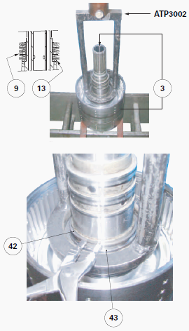
Place the bell housing shaft (3) on a table press with its splines
facing upwards.Using a hydraulic press and service tool ref. ATP3002, compress the ten
Belleville washers (9).
Remove: the snap ring (42); the countersunk thrust washer (43). De-compress the hydraulic press ram. Remove the tool. Make a note of the layout of the Belleville washers.
Remove them from
their clutch bell housing with the thrust washer (13).
Gently drive out the piston (14) using compressed air. Remove and
discard the Quadring seals (15) (16).
Disassembling the forward multidisc clutch
Turn over the Power Shuttle. Place it on a table press with the bell
housing shaft (3) facing downwards.
The principle for removing the discs, intermediate plates and Belleville
washers for the forward clutch is similar to the principle for removing
the reverse clutch.
Remove: the circlip (25); the cover plate (26) fitted with the snap ring
(27) and the hub (28); the discs (21) and intermediate plates (22).
Compress the Belleville washers (20) using a hydraulic press and the
service tool used for the reverse clutch.
Remove: the snap ring (30); the countersunk thrust washer (29).
De-compress the hydraulic press ram. Remove the tool.
Make a note of the layout of the Belleville washers. Remove them from
their clutch bell housing with the thrust washer (45).
Gently drive out the piston (18) using compressed air. Remove and
discard the Quadring seals (17) (19).
Remove: the seal holder (31). Discard the "O" ring (32) and the seal
ring (24); the ball bearing (23). If necessary, drive out the needle
roller bearing (44).
Reassembling the reverse multidisc clutch
Clean and check all components. Replace those that are defective.
On the bell housing shaft (3), clean mainly: the hydraulic channels of
the reverse (14) and forward (18) pistons; the radial lubricating holes.
Lubricate the new Quadring seals (15) (16) and the bore of the clutch
bell housing concerned. The Quadring seals are square seals.
Fit the seals into the grooves of the piston (14) without twisting them.
Position the piston in its clutch bell housing.
Gradually fit it in place, tapping alternately on its rim using a
plastic fitting drift.
On the bell housing shaft (3), slide and position; the thrust
washer (13); the ten Belleville washers (9) according to the layout
noted in step.
On the bell
housing shaft (3), position: the countersunk thrust washer
(43) against the set of Belleville washers; the snap ring (42) in the
recess of the countersunk
thrust washer.
De-compress the hydraulic press ram. Remove tools.
On the bell housing shaft (3), lightly smear grooves of the seal rings
(41) with miscible grease.
Fix a new seal ring inside the base of each groove, ensuring that it
does not exceed the circumference of the bell housing shaft.
Fit: the circlip (8); the ball bearing (1); the snap ring
(104); the thrust plate (102).
Lightly smear the thread of the M6 screws (101) with Loctite 242 or
equivalent. Tighten to a torque of 16 Nm.
Check that the unit (12) rotates freely (hub/reverse driving gear).
Refitting the MF 5612, 5610 forward multidisc clutch
Clean and check all components. Replace those that are defective.
Check that the rivets (33) are present on the rear end of the bell
housing shaft (3).
If removed, fit a new needle roller bearing (44) inside the bell housing
shaft (3) using a suitable fitting drift. Check that the needles rotate
freely.
Lubricate the Quadring seals (17) (19) and the bore of the clutch bell housing concerned. The Quadring seals are square seals. Fit the seals into the grooves of the piston (18) without twisting them. Position the piston in its clutch bell housing.
Gradually fit it in
place, tapping alternately on its rim using a plastic fitting drift.
On the bell housing shaft (3), slide and position: the thrust
washer (45); the ten Belleville washers (20) according to the layout
noted in step.
On the bell housing shaft (3), position: the countersunk thrust washer
(29) against the set of Belleville washers; the snap ring (30) in the
recess of the thrust washer.
De-compress the hydraulic press ram. Remove tools. Smear the "O" ring
(32) and the seal ring (24) with miscible grease. Position them in their
respective groove
on the seal holder (31).
Slide the complete ball bearing (23) and seal holder (31) into the bore
of the bell housing shaft (3). If the discs (21) are to be replaced,
soak the new discs in clean
transmission oil for approximately one hour.
Check that they are well impregnated with oil before fitting them. Start assembly by fitting an intermediate plate against the piston (18) and alternate until the new intermediate plates (22) and new discs (21) (new or re-used depending on the situation) are fitted.
The fitting should end
with a disc (new or re-used, depending on the situation) against the
cover plate (26).
Fit: the cover plate (26) fitted with the snap ring (27); the circlip
(25). Check that the clutch hub (28) rotates freely.
Place the Power Shuttle in a vertical position on a suitable support S.
Fit the rear cover plate (52) of the Dynashift module to the Power
Shuttle.
Lightly smear the thread of the M8 screws (103) with Loctite 242 or
equivalent. Tighten to a torque of 37 Nm.
Refit clutch O/brake N of the Dynashift module.
Close the Powershift module between the housing (111) and the rear cover
plate (52) of the Dynashift module.
Refit the Powershift module. Fit housing C1 to the engine. Reconnect the tractor between housing C of the robotic gearbox and housing C1 of the Powershift module. Calibrate the Power Shuttle. Carry out a road test on the Power Shuttle.
________________________________________________________________________________
 SPECS
SPECS LOADERS
 MAINTENANCE
 PROBLEMS
________________________________________________________________________________________
 MF 1523
 MF 1531
 MF 135
 MF 1547
 MF 1635
________________________________________________________________________________________
 231
231 231S
231S 235
235 240
240 241
241________________________________________________________________________________________
 255
255 265
265 274
274 285
285 375
375________________________________________________________________________________________
________________________________________________________________________________________
 916X Loader
 921X Loader
 926X Loader
 931X Loader
 936X Loader
________________________________________________________________________________________
 941X Loader
 946X Loader
 951X Loader
 956X Loader
 988 Loader
________________________________________________________________________________________
 1655
1655 GS1705
 1742
1742 2635
2635 4608
4608________________________________________________________________________________________
 1080
1080 1100
1100 2615
2615 3050
3050 3060
3060________________________________________________________________________________________
 4708
4708 5455
5455 5450
5450 5610
5610 5613
5613________________________________________________________________________________________
 DL95 Loader
 DL100 Loader
 DL120 Loader
 DL125 Loader
 DL130 Loader
________________________________________________________________________________________
 DL135 Loader
 DL250 Loader
 DL260 Loader
 L90 Loader
 L100 Loader
________________________________________________________________________________________
 6499
6499 7480
7480 7618
7618 7726
7726 1533
1533________________________________________________________________________________________
 2604H
2604H 2607H
2607H 4455
4455 4610M
4610M 4710
4710________________________________________________________________________________________
 L105E Loader
 L210 Loader
 1014 Loader
 1016 Loader
 1462 Loader
________________________________________________________________________________________
 1525 Loader
 1530 Loader
 232 Loader
 838 Loader
 848 Loader
________________________________________________________________________________________
 5712SL
 6713
6713 6715S
6715S 7475
7475 7615
7615________________________________________________________________________________________
 7716
7716 7724
7724 8240
8240 8650
8650 8732
8732________________________________________________________________________________________
 246 Loader
 1036 Loader
 1038 Loader
 1080 Loader
 856 Loader