
________________________________________________________________________________
Massey Ferguson 5608, 5609 gearbox - Powershift module
Drain the transmission oil. Split the Massey Ferguson 5608, 5609 tractor between the engine and the gearbox.
Remove: either the complete gearbox (if servicing is to be carried out
on the whole transmission assembly) or only the Powershift module from
the unit, leaving the mechanical unit coupled to the rear axle (if
servicing is to be carried out on the Powershift module or reverse
shuttle only)
Remove:
- all hydraulic pipes fitted to the unit housing.
- the unit control hydraulic unit with its connecting pipes.
- the union and the lubrication pipe of the Powershift module.
- the PTO shaft.
If the whole unit has been removed, separate the Powershift module from
the mechanical gearbox. Rig up four makeshift legs on which to set the
unit vertically.
Use an M14 screw or threaded rod, and weld on a nut to ensure a minimum
distance of 120 mm between the unit and the work surface.
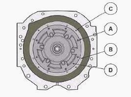
Unscrew the two diametrically opposed screws (A) and replace them with
two shackles to sling the gearbox. do not remove screws (C). They hold
the front
epicyclic gear train housing (D) in place.
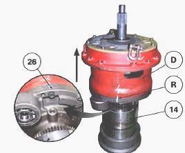
Sling the MF 5608, 5609 gearbox Powershift module using the shackles.
Make a mark (R) on the housings to ensure the modules are refitted
correctly.
Install the Powershift module on a supporting fixture positioned on the
forward clutch.
Take out the screws holding the cover (26) on the housing (D).
Using the sling, lift and separate the front part of the Powershift
module.
During this step, the brake, the clutch and the rear planet carrier stay
on the Power Shuttle.
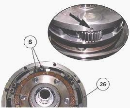
Sling the Powershift module. Check that the return springs (S) are
present in the cover (26).
Carry out step in reverse order, aligning the two parts using the mark
(R).
Take care when inserting the planetary gears in the Powershift module
brake piston (57).
Install the cover screws (26) to the Powershift module, after smearing
them with Loctite 242 or equivalent. Tighten the screws to a torque of
66 Nm.
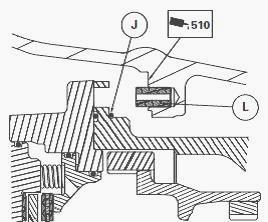
Clean the mating faces then apply Loctite 510 or equivalent sealing product. Reinstall the "O" ring (J). Grease it lightly and Install it on the Powershift module.
Sling the
reverse shuttle and Powershift module assembly.
Install the assembly in the unit housing. Lower the sling, aligning the
centring pin (L) with the port. Reinstall the screws (B) of the housing
(D).
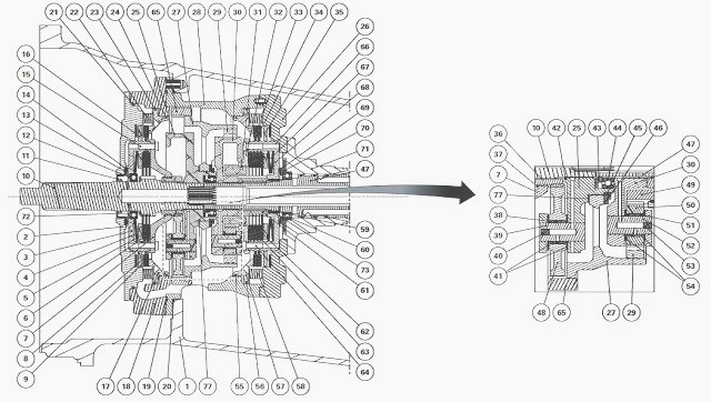
Removing the Powershift module
Remove the piston (57) and the springs (58). Place the section with the
reverse shuttle on a suitable supporting fixture, with the cover (26)
and planet carrier (30)
facing upwards. Remove the planet carrier (30).
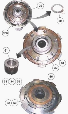
To remove the planetary gears. Take out the clutch O/brake N assembly
from the cover (26). Retain the friction washer (69). Remove the clutch
hub (61). Take out
the screws (64) to remove the clutch cover (32).
Mark the order of the discs and brake/clutch thrust plates before
removing them. Mark the direction and remove the Belleville washers (67)
and (68).
If necessary, take out the needle bearing (73) of the clutch housing
(66).
Place the front part of the Massey Ferguson 5609, 5608 gearbox
Powershift module facing downwards on a suitable supporting fixture.
Make a mark (G) on the
housings (28) and (18).
Remove the screws from the housings (28) and (18), then remove the
housing (28). Take out and discard the "O" rings (74) and (75) on the
housing pilot ports.
Discard "O" ring (19) and "O" ring (76).
Remove the ring gear carrier assembly (27), the two ring gears (29) and
(65), with the front planet carrier. Remove the circlip (46). Separate
the front planet carrier
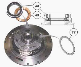
from the ring gears. Retain the spacer (45). Remove the bearing (44),
the washer (77) and the spacer (43) from the planet carrier (25).
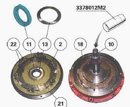
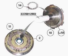
To remove the planetary gears. Place the housing (18) on the shims, with
the input shaft (10) facing upwards. Place service tool on the input
shaft (10) so as to
protect the lip seal (11). Unscrew the cover screws (2) of the housing
(18). Remove the cover (2) and retain the springs (22). Discard the "O"
ring (21).
Remove the brake piston (17) from the housing (18). Discard the "O"
rings (23) and (24). Remove the friction washer (13). Remove the lip
seal (11). Remove the
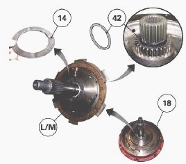
clutch M/brake L assembly from the housing (18). Remove the friction
washer (14) and the snap ring (42).
Place the clutch M/brake L assembly on a supporting fixture. Take out
the screws (15) to remove the clutch cover (7).
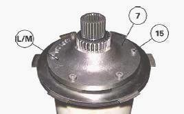
If necessary, take out the snap ring (37) to separate the sun gear (36)
from the clutch cover (7). Mark the order of the discs and brake/clutch
thrust plates. Remove
the discs (5) and thrust plates (6) of clutch M and the discs (8) and
thrust plates (9) of brake L.
Remove the junction plate (16). Mark the
assembly order then
remove the input shaft (10), the Belleville washer (4), the spring
washer (72) and the bearing (12).
Install the Powershift module
Ensure all parts are in good condition. Ensure the clutch pilot ports
and lubricating ports are clean. Install a new oiled "O" ring on the
Powershift module cover.
In the cover (2), fit a new lip seal (11) smeared with grease on the
inside and oiled on the outside. Install the springs in the housings.
Install a disc on the cover.
If the MF 5608, 5609 brake discs or clutch discs have been replaced,
they must be soaked for approximately one hour in a transmission oil
bath.
Install the friction washer (13), with the grease removed and smeared
with Loctite 648 or equivalent.
Install the Belleville washer (4), the ball bearing (12) and the spring
washer (72) on the clutch housing (3). Slide on the shaft (10). Install
the junction plate (16), the
clutch discs (5) and thrust plates (6), and a brake disc (8) and thrust
plate (9) on the clutch housing (3).
Reinstall the clutch cover (7). Install the screws (15) smeared with
Loctite 242. Tighten to a torque of 33 Nm. Install the snap ring (42) on
the shaft (10). Install the
friction washer (14) smeared with grease on the clutch housing (3).
Install service tool on the input shaft (10) so as to protect the lip
seal (11). Install clutch M /brake L on the cover (2), paying attention
to the lip seal (11). Place the
cover (2) on a supporting fixture to position the input shaft (10).
Replace the last disc (8) of brake L. Install the brake piston (17) with
new, oiled "O" rings (23) (24), in the housing(18). Reinstall the
housing (18) on the cover (2).
Install the cover screws smeared with Loctite 242. Tighten to a torque
of 29-37 Nm. Place the planet carrier (25) on the input shaft (10).
Turn the planetary gears (48) to engage them with the sun gear (36) and
line up the splines of the planet carrier on the shaft. Insert the
spacer (43,) which should be
smeared with grease, and the ball bearing (44) in the planet carrier
(25). Install the friction washer (77).
Position the ring gears (29) (65) and ring gear carrier (27) assembly on
the planet carrier (25). Install the spacer (45) and the circlip (46).
Smear new "O" rings (76)
and (19) with miscible grease and Install them on the housing (28).
Using a sling, position housing (28) on housing (18).
Make sure that the "O" rings are correctly positioned. Install and
tighten the housing screws (18) and (28), smeared with Loctite 242.
Insert the brake piston (57),
fitted with two new oiled "O" rings (55) (56), in the housing (28).
Install two shims in the housing (28) to hold the ring gears and the
planet carrier in place during assembly of the module and the reverse
shuttle. Check that the
needle bearing (73) is present in the MF 5609, 5608 clutch housing (66).
Check its condition and change it if necessary.
Install the friction washer (69), smeared with grease, on the cover
(26). Install a brake disc (33). Install the clutch housing (66) on the
cover (26), followed by the hub
(61), the Belleville washers (67) (68) and the junction plate (35).
Install the clutch discs (63) and thrust plates (62).
If the brake discs or clutch discs have been replaced, they must be
soaked for approximately one hour in a transmission oil bath. Install
the brake discs (33) and
thrust plates (34).
Install the clutch cover (32), the screws (64), smeared with Loctite
242, and tighten them to a torque of 33 Nm. Install the springs (58) in
the cover (26). Install the
planet carrier (30) on the output shaft (47). Reinstall the Powershift
module on the reverse shuttle.
Disassembling and reassembling the planetary gears
The planetary gear pins are fitted already tightened in the thickest
part of the planet carriers. The pins comprise lubricating ports that
must be positioned facing the
corresponding ports on the planet carrier.The disassembly principle is
the same for all planet carriers.
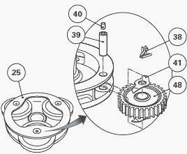
The following example applies to planetary gears in the front epicyclic
gear train of the Powershift module. Place the planet carrier (25) in a
vice equipped with
protective jaws. Using a suitable press and fixture, drive out the pins
(39) from the planet carrier (25), pushing from the side where the
planet carrier is thickest.
Take out the planetary gear and retain the friction washers (41) and
bearing needles (38). Clean all the parts, check their condition and
replace any that are
defective. Ensure the lubricating ports of the planet carriers and pins
are clean.
The pins of the planetary gears (39) are blocked by plugs (40). Check
that the plugs are present. Install new ones if any are missing. Prepare
the planetary gears.
Install the bearing needles in the planetary gears using miscible
grease. Place the planet carrier on a suitable supporting fixture.
Install the planetary gear (48) with the needle bearing (38) and the two
friction bearings (41). Insert the pin (39), then drive it in, using a
suitable press and fixture.
Insert the pin until it is flush with the planet carrier surface. Check
that the planetary gears rotate freely.
Reinstall the PTO shaft (33). Clean and check the condition of the
Massey Ferguson 5608, 5609 gearbox hydraulic control unit.
Check for the presence of "O" rings in the hydraulic unit ports. If the
"O" rings have to be replaced, oil them slightly. Apply Loctite 510 or
an equivalent sealing
product to the mating face of the unit. Reinstall the connecting pipes,
then the hydraulic control unit. Install the screws.
Assemble the gearbox and the engine and rear axle. Top up the
transmission oil level. Carry out a clutch calibration procedure. Carry
out road tests to check the
operation of the gearbox. Check the operation of the hydraulics and make
sure that there are no leaks.
________________________________________________________________________________
________________________________________________________________________________________
 SPECS
SPECS LOADERS
 MAINTENANCE
 PROBLEMS
________________________________________________________________________________________
 MF 1523
 MF 1531
 MF 135
 MF 1547
 MF 1635
________________________________________________________________________________________
________________________________________________________________________________________
 231
231 231S
231S 235
235 240
240 241
241________________________________________________________________________________________
 255
255 265
265 274
274 285
285 375
375________________________________________________________________________________________
________________________________________________________________________________________
 916X Loader
 921X Loader
 926X Loader
 931X Loader
 936X Loader
________________________________________________________________________________________
 941X Loader
 946X Loader
 951X Loader
 956X Loader
 988 Loader
________________________________________________________________________________________
 1655
1655 GS1705
 1742
1742 2635
2635 4608
4608________________________________________________________________________________________
 1080
1080 1100
1100 2615
2615 3050
3050 3060
3060________________________________________________________________________________________
 4708
4708 5455
5455 5450
5450 5610
5610 5613
5613________________________________________________________________________________________
 DL95 Loader
 DL100 Loader
 DL120 Loader
 DL125 Loader
 DL130 Loader
________________________________________________________________________________________
 DL135 Loader
 DL250 Loader
 DL260 Loader
 L90 Loader
 L100 Loader
________________________________________________________________________________________
 6499
6499 7480
7480 7618
7618 7726
7726 1533
1533________________________________________________________________________________________
 2604H
2604H 2607H
2607H 4455
4455 4610M
4610M 4710
4710________________________________________________________________________________________
 L105E Loader
 L210 Loader
 1014 Loader
 1016 Loader
 1462 Loader
________________________________________________________________________________________
 1525 Loader
 1530 Loader
 232 Loader
 838 Loader
 848 Loader
________________________________________________________________________________________
 5712SL
 6713
6713 6715S
6715S 7475
7475 7615
7615________________________________________________________________________________________
 7716
7716 7724
7724 8240
8240 8650
8650 8732
8732________________________________________________________________________________________
 246 Loader
 1036 Loader
 1038 Loader
 1080 Loader
 856 Loader