________________________________________________________________________________
Massey Ferguson 6180, 6190 hydraulic system - Auxiliary spool valves
The Rexroth SM12 auxiliary spool valves are fitted on the high flow rate circuit. They are fed by oil coming from the trailer braking valve or the closing plate fitted in its place (depending on version).
When the spool valves are not activated, the oil is available for the lift control valve fitted downstream. The Massey Ferguson 6180, 6190 tractor auxiliary spool valves are mounted on a support which is itself fitted to the rear of the lift cover.
Quick-disconnect couplings are fitted directly on the spool valve body.
To obtain sufficient distance between couplings, the spool valves are
fitted with blocks serving as spacers. These blocks are also used to let
the oil flow to the next spool.
Available sets of MF 6180, 6190 spool valves
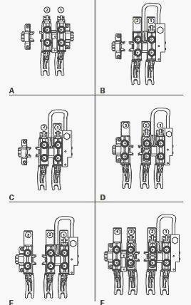
Set A - 2 spool valves
- Spool valve 1 and 2: 3-position, SA / DA with spring loaded return to
neutral
Set B - 2 spool valves and flow divider
- Spool valve 1: 3-position, SA / DA with automatic return to neutral
- Spool valve 2: 4-position, DA with automatic return to neutral
Set C - 2 spool valves and flow divider
- Spool valve 1: 3-position, SA / DA with automatic return to neutral
- Spool valve 2: 3-position, SA / DA and zero leakage
Set D - 3 spool valves and flow divider
- Spool valve 1: 3-position, SA / DA with spring loaded return to
neutral
- Spool valve 2: 3-position, SA / DA with automatic return to neutral
and zero leakage
- Spool valve 3: 4-position, DA with automatic return to neutral
Set E - 3 spool valves and flow divider
- Spool valve 1: 3-position, SA / DA with automatic return to neutral
- Spool valve 2 and 3: 4-position, DA with automatic return to neutral
Set F - 4 spool valves and flow divider
- Spool valve 1: 3-position, SA / DA with spring loaded return to
neutral
- Spool valve 2 and 3: 3-position, SA / DA with automatic return to
neutral and zero leakage
- Spool valve 4: 4-position, DA with automatic return to neutral
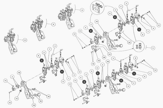
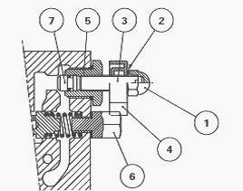
(1) Inlet unit with flow control valve (2) Plates with seals (3) Excess
flow rate pipe (4) Adjustment knob (flow divider) (5) Single / double
acting (SA / DA) change-over screw (6) Spool valves (all versions) (7) Intermediate block
(excess flow rate) (8) Set (2, 3 or 4 spool valves)
(9) Intermediate block (10) Support (11) End plate (connection with lift
control valve) (12) Screw (13) Plug and seal (provisional return) (14)
Screw (15) Cap and seal
(filling) (16) Plug and seal (provisional return) (17) Studs and nuts
(18) Pin (19) Stirrup (20) Pin (21) Support (control cable) (22) Screw
Massey Ferguson 6190, 6180 spool valves characteristics
Functions: Double acting; Single and double acting (convertible).
These functions are also recognised via the abbreviations SA and DA.
Positions: Three; Four with one in floating position.
Return to neutral: By spring or by an automatic system.
Zero leak: With or without.
Each spool valve is activated by a lever in the cab and it has three
phases of travel:
- 35% reduced flow rate;
- 45% progressive increase of flow rate and pressure;
- 20% full flow rate.
The spool valve placed against the flow divider is spool valve No.1. The progressive increase of flow rate and pressure ensures uniform operation of the MF 6180, 6190 implements.
This characteristic also
allows two spool valves to
be activated simultaneously, the total flow rate being shared. The flow
rate to each quick-disconnect coupling is proportional to the position
of the control lever.
Operating and adjusting the flow divider
Function of the flow divider
For operations requiring low oil flow rate, the flow divider allows to
vary supply to the hydraulic slave device via a knob (4) used to adjust
flow rate between
“maximum stop” and “minimum stop”.
It is fitted at the inlet of the MF
6190, 6180 tractor auxiliary spool valve assembly. It is supplied by oil
from the high flow rate
circuit passing through the trailer braking valve or the closing plate
(depending on version).
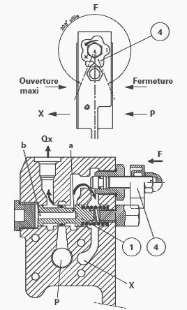
Operation
The oil coming from port (P) is directed to port (X) and supplies the
first spool valve. The flow is regulated according to the position of
the knob (4). Simultaneously,
the pressure in channel (P) allows oil to pass through drilled hole (a)
and restrictor (b).
The piston (1) is then moved to the right, allowing
oil to be directed towards
port (Qx). The intermediate block (7) receives the excess flow rate via
the pipe (3).
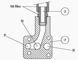
Adjustment
Remove the stop screw (6), the locknut (1) and the washer (2).
Unscrew and remove the knob (4).
Without forcing the screw (3), tighten it until the valve (7) abuts
against its seat. Place the knob (4) in contact with the sleeve (5).
Unscrew the knob two full turns. Install and tighten the stop screw (6)
to a torque of 20 Nm. Turn the knob to its closed position.
Install washer (2) and tighten the locknut (1) to a torque of 30 - 40 Nm.
________________________________________________________________________________
 SPECS
SPECS LOADERS
 MAINTENANCE
 PROBLEMS
________________________________________________________________________________________
 MF 1523
 MF 1531
 MF 135
 MF 1547
 MF 1635
________________________________________________________________________________________
 231
231 231S
231S 235
235 240
240 241
241________________________________________________________________________________________
 255
255 265
265 274
274 285
285 375
375________________________________________________________________________________________
________________________________________________________________________________________
 916X Loader
 921X Loader
 926X Loader
 931X Loader
 936X Loader
________________________________________________________________________________________
 941X Loader
 946X Loader
 951X Loader
 956X Loader
 988 Loader
________________________________________________________________________________________
 1655
1655 GS1705
 1742
1742 2635
2635 4608
4608________________________________________________________________________________________
 1080
1080 1100
1100 2615
2615 3050
3050 3060
3060________________________________________________________________________________________
 4708
4708 5455
5455 5450
5450 5610
5610 5613
5613________________________________________________________________________________________
 DL95 Loader
 DL100 Loader
 DL120 Loader
 DL125 Loader
 DL130 Loader
________________________________________________________________________________________
 DL135 Loader
 DL250 Loader
 DL260 Loader
 L90 Loader
 L100 Loader
________________________________________________________________________________________
 6499
6499 7480
7480 7618
7618 7726
7726 1533
1533________________________________________________________________________________________
 2604H
2604H 2607H
2607H 4455
4455 4610M
4610M 4710
4710________________________________________________________________________________________
 L105E Loader
 L210 Loader
 1014 Loader
 1016 Loader
 1462 Loader
________________________________________________________________________________________
 1525 Loader
 1530 Loader
 232 Loader
 838 Loader
 848 Loader
________________________________________________________________________________________
 5712SL
 6713
6713 6715S
6715S 7475
7475 7615
7615________________________________________________________________________________________
 7716
7716 7724
7724 8240
8240 8650
8650 8732
8732________________________________________________________________________________________
 246 Loader
 1036 Loader
 1038 Loader
 1080 Loader
 856 Loader