________________________________________________________________________________
Massey Ferguson 6120, 6130 auxiliary spool valves - Removing and install
Auxiliary spool valves can be removed and refitted directly on MF 6120,
6130 tractor by removing each unit and leaving only the main support
fitted to the lift cover.
Remove unit(s) close to the auxiliary spool valves which might obstruct
access to them. (Example: hydraulic valve for automatic hook).
Disconnect:
- the supply hose from the right-hand hydraulic cover;
- the outlet hose to the lift control spool valve.
Separate the control cables of the supports and spool valves.
Removal
Remove the locknuts located at the end of the spool valve set.
Release and remove each hydraulic component after visually noting its
position.
The spool valves are fitted either side of the main support.
If necessary:
- Remove quick-disconnect couplings.
- Remove pins and screws. Separate the cable support from the spool
valve.
Install
Reinstalling operations are not difficult. They therefore require
carrying out the removal operations in reverse order.
However, during refitting it is necessary to ensure that:
- parts to be assembled are not dirty, corroded, dented, etc.
- seals are oiled.
The locknuts fitted at the end of the spool valve set should be
tightened to a torque of 30 - 33 Nm.
Check the correct operation of each spool valve on the two, three or
four positions (depending on model).
Check the pressure on quick-disconnect couplings.
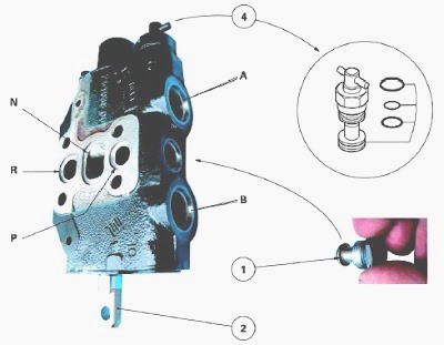
3-position spool valve, SA / DA with spring loaded return to neutral
Oil from the high flow rate circuit passes through the trailer braking
valve (if fitted) or closing plate fitted to the right-hand hydraulic
cover and supplies the various
spool valves via the continuity channel.
The spool valves are fitted in
series in priority over the linkage.
Neutral position
Oil is not available from outlets (A) or (B).
Oil is directed via the
continuity channel (N) to the lift control valve and passes directly to
the suction manifold of the pump
when the linkage is in neutral position.
Channels (N) and (P) are linked in the intermediate block to supply the
subsequent spool valves.
Inlet - outlet position
When the spool (2) is moved upwards or downwards, the continuity channel
is cut, the pressure increases and raises the valve (1).
The oil is then directed to the internal channels via grooves located on the spool. Depending on the spool position, outlets (A) or (B) are supplied.
Simultaneously, the oil
returning from the ram is
directed depending on the position of the spool, to outlets (A) or (B)
to reach the return channel (R).
Single / double acting change-over
To obtain the single acting position, unscrew the valve (4).
The outlet (A) then opens into the channel (R), and the outlet (B) supplies the hydraulic slave device.
To
obtain the double acting position, screw in the valve (4).
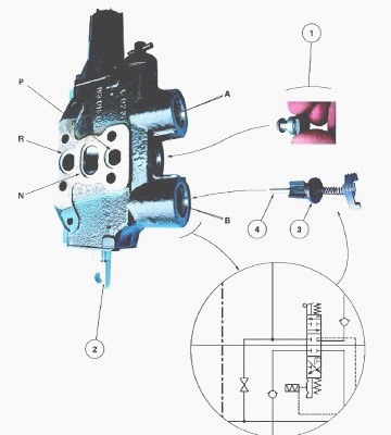
3-position spool valve, SA / DA with automatic return to neutral
Neutral position
The operating principle of the Massey Ferguson 6130, 6120 3-position
single or double acting spool valve with automatic return to neutral, is
the same as for the
previous 3-position SA / DA spool valve with spring loaded return to
neutral.
Inlet - outlet position
Operation is identical to the 3-position SA / DA spool valve with spring
loaded return to neutral, with automatic return to neutral as an added
feature. A system
placed in the unit locks when the spool is activated.
The spool returns
automatically when Massey Ferguson 6120, 6130 tractor hydraulic pressure
reaches 150 -
170 bar. The pressure passes through bores machined in the spool. It
then releases a system comprised of balls and springs allowing the
automatic return of the
spool to neutral.
The unit is joined to channel. A residual pressure in
the unit (greater than 2 bar) may cause undue return of the spool to
neutral.
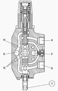
3-position SA / DA spool valve with non-return valve and automatic
return
The operation of this spool valve is identical to those explained
previously.
Operation of the non-return valve
When the spool (2) is moved upwards, the oil coming from channels (N)
and (P) is directed to outlet (B) by lifting the non-return valve (3)
which supplies the slave
device. In the neutral position, the non-return valve ensures the oil
tightness of the circuit.
When the spool is moved upwards, the oil coming from the channels (N) and (P) lifts the valve (1). It is then directed to an internal channel via grooves machined on the spool, and supplies the slave device via the outlet (A).
The movement of the spool shifts the pushrod (4). This raises the ball, causing a drop in pressure on the slave device side, which allows the valve (3) to rise from its seat and oil to flow through to the channel (R).
During disassembly of
the spool (2), it is essential to first disassemble the non-return valve
(3) and pushrod (4).
4-position DA spool valve, with automatic return to neutral and floating
position
When the spool (2) is moved upwards or downwards, the same positions are
obtained as in the previous spool valves.
The MF 6130, 6120 4-position DA spool valve with automatic return to neutral and floating position has an added feature: a floating position (F) when the spool has moved its maximum distance out of the automatic return to neutral position.
In this position (F), the outlet
channels (A) and (B) open into the return channel (R). The oil then
circulates freely.
Assembling and adjusting a control cable
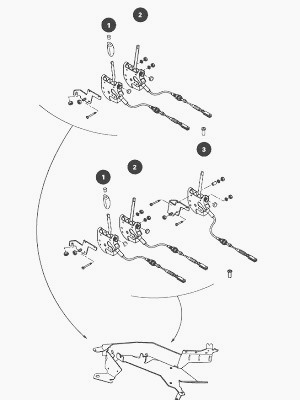
Cab side
The numbers (1) to (3) indicate the location of the levers on the
console.
The console design allows the assembly of a fourth spool valve.
The control unit is designed to incorporate the lever and cable.
After assembling the unit, move the control lever to neutral position.
Spool valve side
If a stirrup needs to be replaced, remove and replace it without turning
the spool of the spool valve.
When assembling, the pins should be lightly smeared with molybdenum
disulfide or AS767 grease or equivalent.
Screw the clevis to the threaded part of the cable.
Attach the clevis to the stirrup using the hook. Tighten nut.
Adjust the stop with the nut.
Tighten nut and check that the cable is not constrained in any way.
Check
Start the tractor engine. Using the relevant lever, check that the three
or four positions of the spool valve (depending on model) engage
correctly.
In case of faulty operation, separate the spool valve control and check the movement of the spool.
If it operates correctly, check the cable adjustment again.
________________________________________________________________________________
 SPECS
SPECS LOADERS
 MAINTENANCE
 PROBLEMS
________________________________________________________________________________________
 MF 1523
 MF 1531
 MF 135
 MF 1547
 MF 1635
________________________________________________________________________________________
 231
231 231S
231S 235
235 240
240 241
241________________________________________________________________________________________
 255
255 265
265 274
274 285
285 375
375________________________________________________________________________________________
________________________________________________________________________________________
 916X Loader
 921X Loader
 926X Loader
 931X Loader
 936X Loader
________________________________________________________________________________________
 941X Loader
 946X Loader
 951X Loader
 956X Loader
 988 Loader
________________________________________________________________________________________
 1655
1655 GS1705
 1742
1742 2635
2635 4608
4608________________________________________________________________________________________
 1080
1080 1100
1100 2615
2615 3050
3050 3060
3060________________________________________________________________________________________
 4708
4708 5455
5455 5450
5450 5610
5610 5613
5613________________________________________________________________________________________
 DL95 Loader
 DL100 Loader
 DL120 Loader
 DL125 Loader
 DL130 Loader
________________________________________________________________________________________
 DL135 Loader
 DL250 Loader
 DL260 Loader
 L90 Loader
 L100 Loader
________________________________________________________________________________________
 6499
6499 7480
7480 7618
7618 7726
7726 1533
1533________________________________________________________________________________________
 2604H
2604H 2607H
2607H 4455
4455 4610M
4610M 4710
4710________________________________________________________________________________________
 L105E Loader
 L210 Loader
 1014 Loader
 1016 Loader
 1462 Loader
________________________________________________________________________________________
 1525 Loader
 1530 Loader
 232 Loader
 838 Loader
 848 Loader
________________________________________________________________________________________
 5712SL
 6713
6713 6715S
6715S 7475
7475 7615
7615________________________________________________________________________________________
 7716
7716 7724
7724 8240
8240 8650
8650 8732
8732________________________________________________________________________________________
 246 Loader
 1036 Loader
 1038 Loader
 1080 Loader
 856 Loader