
________________________________________________________________________________
Massey Ferguson 6160, 6170, 6180 transmission - Dynashift
The Dynashift is fixed on the front of the input unit. It is an hydraulically controlled gear shifting device that provides Massey Ferguson 6180, 6170 tractor transmission input ratios.
This function is provided by two epicyclic gear trains associated with two hydraulic clutches.
The design of the Dynashift allows selecting the four ratios while moving, without needing to disengage the clutch, using a lever located under the steering wheel.
The Dynashift unit is controlled by two solenoid valves installed on the
low-pressure hydraulic line (17 bar).
Both solenoid valves are monitored by the MF
6180, 6170, 6160 tractor’s electronic system:
- the primary epicyclic train, the main part of the input unit, used to
transfer movement from the engine to the gearbox.
- the secondary epicyclic train, for controlling the speed of the
primary sun gear.
Primary epicyclic train
The movement comes in via primary ring gear (31) which is splined onto
MF 6160, 6180 transmission shaft (7).
This turns at the same speed as the engine. The movement exits via planet pinion cage (28) which is splined onto secondary shaft (53).
Primary sun gear (64) is driven by the secondary epicyclic train.
The speed
of this sun gear determines the reduction ratio of the box.
Secondary epicyclic train
This epicyclic train is controlled by Massey Ferguson 6170, 6180
hydraulic clutches and brakes.
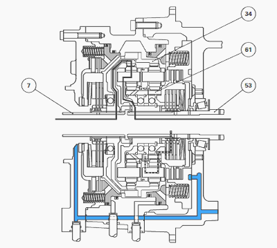
Secondary ring gear (34) is:
- either locked to transmission shaft (7) by three clutch discs (3) and
cup washer (4) located in the front part of the unit,
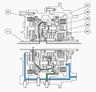
- or locked in relation to the unit by three brake discs (15) and piston
(22).
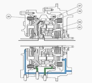
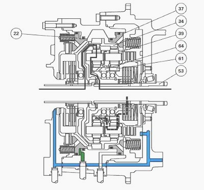
When not actuated, piston (22) is drawn backwards by twelve springs (20)
and cup washer (4) via thrust plate (16).
When it is actuated under
pressure from the 17-bar circuit, piston (22) moves forwards, blocking brake discs (15) and
pushing plate (16), which compresses cup washer (4).
The speed of the secondary ring gear stabilizes as follows:
- speed equal to the engine speed when the front piston is not actuated,
- speed null when the front piston is actuated.
Secondary sun gear is either:
- locked on the secondary shaft by means of four clutch discs (50) and
two cup washers (52) located on the rear part of the unit, or
- immobilized in relation to the unit by means of three brake discs (41)
and piston (37).
When not actuated, piston (37) is pushed forwards by the cup washers and
six springs (65). Under the effect of the 17-bar pressure, piston (37)
moves towards the
rear and blocks brake discs (41).
It compresses cup washers (52) through
the action of thrust plate (45), which frees the clutch discs on the
secondary shaft.
By immobilizing secondary ring gear (34) or secondary sun gear (61), the speed of secondary planet-pinion cage (39) is modified.
The secondary
planet-pinion cage drives primary sun gear (64), which establishes the
reduction ratio of the box.
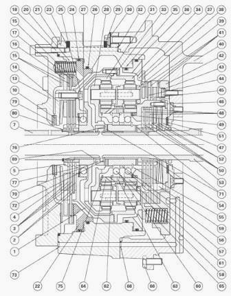
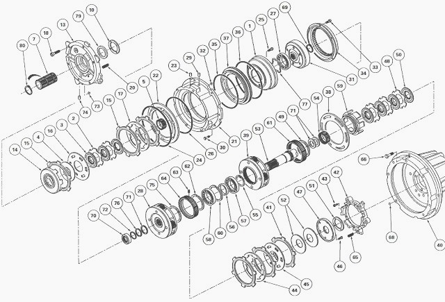
MF 6160, 6170 transmission - Dynashift
(1) Secondary ring gear carrier (2) Intermediate plates (3) Clutch discs
(4) Cup washer (5) Splined hub (7) Transmission shaft (10) Friction
washer (13) Front cover
(14) Clutch housing (15) Front brake discs (16) Thrust plate (clutch -
brake) (17) Clutch plate (18) Screw (20) Springs (21) Spacer housing
(22) Piston (23) Rivet
(24) O’ring (25) Screw (26) O’ring (27) Ball bearing
(28) Primary planet pinion cage (29) Rivet (30) Screw (31) Primary ring
gear (32) O’ring (33) Screw (34) Secondary ring gear (35) O’ring (36)
O’ring (37) Rear
piston (38) Clutch plate (39) Secondary planet pinion cage (40) Reverse
shuttle unit (41) Rear brake discs (42) Housing (43) Screw (44) Clutch
plate (45) Thrust
plate (clutch-brake) (46) Screw (47) Cover (48) Intermediate plates (49)
Retaining ring (50) Rear clutch discs (51) Friction washer (52) Cup
washers (53)
Secondary shaft (54) Splined hub (55) Circlip (56) Spacer
(57) Ball bearing (58) Ball bearing (59) Rear clutch housing (60)
Retaining ring (61) Secondary sun gear (62) Retaining ring (63) Needles
(64) Primary sun gear (65)
Springs (66) Screw (68) O’ring (69) Circlip (70) Stop (71) Shim(s) (72)
Retaining ring (73) O’ring (74) Plug (75) Oil splasher (76) Stud washer
(77) Spring washer
(79) Washer (80) Circlip
Explanation of MF 6180, 6160 tractor gearbox ratios
Ratio A: 1/1.620 reduction
Pistons (22) and (37) simultaneously receive the pressure of the 17-bar
circuit. Secondary ring gear (34) is locked to the housing by the action
of the front brake.
Secondary sun gear (61) is locked to the housing by the action of the rear brake. Consequently, the secondary epicyclic train is locked. Primary sun gear (64) is blocked.
The reduction ratio is determined by the primary epicyclic
train only. The kinematics are conventional, the movement entering via
the ring gear and exiting
via the planet pinion cage, with the sun gear remaining fixed.
Ratio B: 1/1.386 reduction
Front piston (22) is under pressure. Secondary ring gear (34) is locked
to the housing by the front brake.
Rear piston (37) is not under pressure.
Secondary sun gear (61) rotates
with secondary shaft (53) (clutch engaged). Secondary planet-pinion cage
(39) turns at low
speed, driving primary sun gear (64). The reduction effect is therefore
lower.
Ratio C: 1/1.1704 reduction
Rear piston (37) receives the pressure. Secondary sun gear (61) is
locked to the housing by the effect of the rear brake. Front piston (22)
is not under pressure.
Secondary ring gear (34) rotates with transmission shaft (7) (clutch engaged), giving a speed higher than that of secondary planet-pinion cage (39).
Primary sun
gear (64) is driven by secondary planetpinion cage (39), at a speed
greater than for ratio B. The reduction effect is therefore lower still.
Ratio D: Ratio 1/1
Neither piston is actuated. Both clutches are therefore engaged.
Secondary ring gear (34) rotates with transmission shaft (7).
Secondary sun gear (61) is locked to secondary shaft (53), resulting in mechanical locking of the complete system.
The ratio is consequently 1:1 (direct transmission).
________________________________________________________________________________
________________________________________________________________________________________
 SPECS
SPECS LOADERS
 MAINTENANCE
 PROBLEMS
________________________________________________________________________________________
 MF 1523
 MF 1531
 MF 135
 MF 1547
 MF 1635
________________________________________________________________________________________
________________________________________________________________________________________
 231
231 231S
231S 235
235 240
240 241
241________________________________________________________________________________________
 255
255 265
265 274
274 285
285 375
375________________________________________________________________________________________
________________________________________________________________________________________
 916X Loader
 921X Loader
 926X Loader
 931X Loader
 936X Loader
________________________________________________________________________________________
 941X Loader
 946X Loader
 951X Loader
 956X Loader
 988 Loader
________________________________________________________________________________________
 1655
1655 GS1705
 1742
1742 2635
2635 4608
4608________________________________________________________________________________________
 1080
1080 1100
1100 2615
2615 3050
3050 3060
3060________________________________________________________________________________________
 4708
4708 5455
5455 5450
5450 5610
5610 5613
5613________________________________________________________________________________________
 DL95 Loader
 DL100 Loader
 DL120 Loader
 DL125 Loader
 DL130 Loader
________________________________________________________________________________________
 DL135 Loader
 DL250 Loader
 DL260 Loader
 L90 Loader
 L100 Loader
________________________________________________________________________________________
 6499
6499 7480
7480 7618
7618 7726
7726 1533
1533________________________________________________________________________________________
 2604H
2604H 2607H
2607H 4455
4455 4610M
4610M 4710
4710________________________________________________________________________________________
 L105E Loader
 L210 Loader
 1014 Loader
 1016 Loader
 1462 Loader
________________________________________________________________________________________
 1525 Loader
 1530 Loader
 232 Loader
 838 Loader
 848 Loader
________________________________________________________________________________________
 5712SL
 6713
6713 6715S
6715S 7475
7475 7615
7615________________________________________________________________________________________
 7716
7716 7724
7724 8240
8240 8650
8650 8732
8732________________________________________________________________________________________
 246 Loader
 1036 Loader
 1038 Loader
 1080 Loader
 856 Loader