________________________________________________________________________________
Massey Ferguson 5400, 6200 series tractors hydraulic system - Right-hand cover plate
Massey Ferguson 6245, 6260, 6265, 5460, 5465
right-hand cover plate is fitted to the rear axle housing and has two
main functions:
- it supports numerous hydraulic system (57 l/min) components.
- it incorporates various suction and cooling channels of the high and
low flow rate systems (high and low pressure).
On its internal face, the cover plate is connected to the:
- two-stage hydraulic pump and its drive gear
- suction pipe
- inlet manifold
- the left-hand cover plate transfer pipe.
On its external faces, it is connected to the:
- four control solenoid valves of the low pressure functions (depending
on option).
- There is a diode in the solenoid of the PTO brake solenoid valve.
- The PTO clutch is controlled by an on/off solenoid valve.
- safety valve in the MF 6245, 6260, 6265 high pressure hydraulic system
- valve for the suspended front axle (if fitted).
- trailer brake valve (if fitted) or a cover plate (depending on option)
- three "diagnostics" connectors
- strainer
- support and main 15 micron filter(s).
- filter switch
- engine speed sensor.
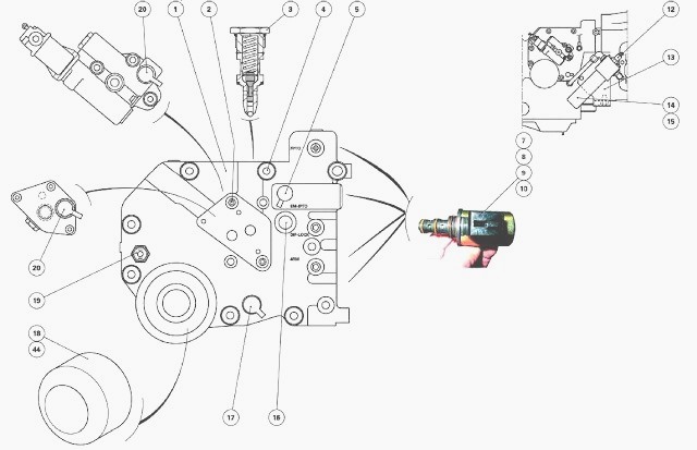
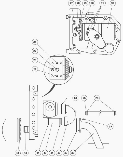
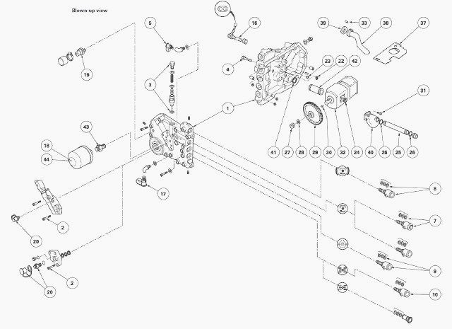
(1) Cover plate (2) Screw (3) High pressure (high flow rate) valve (4)
Screw
(5) Low pressure 20 bar diagnostics connector (7) On/off solenoid valve
(PTO clutch) (8) to (10) Solenoid valves: PTO brake, front and rear
differential lock, 4WD
(12) Blockage indicator
(13) Support (14) Filters (15) 15 micron filter cartridges (16) Engine
speed sensor (17) Low flow rate diagnostics connector (18) Strainer (19)
Filter switch
(20) High pressure, high flow rate diagnostics connector (21) Centring
pins (22) "O" ring (23) "O" ring (24) Seal (25) Transfer pipe (26) "O"
rings (27) Nut (28)
Washer (29) Gear (30) Key (31) Screw
(32) Hydraulic pump (33) Pin (37) Deflector (38) Suction pipe (39) Seal
(40) Inlet manifold (41) "O" rings (42) Pipe (43) Threaded end fitting
(44) Seal
Identification of channels and ports
On the cover plate
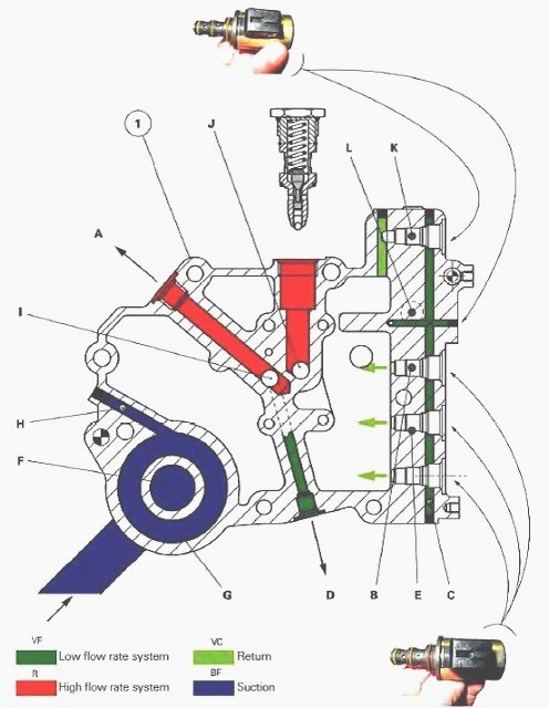
A - Channel to Massey Ferguson 6260, 6265, 5465 auxiliary spool valves,
B - Port to front and rear differential locks (if fitted), C - 20 bar
pressure inlet from left-hand hydraulic cover plate, D - Low flow rate channel to main filters
(15 microns) and Orbitrol spool valve, E - Port to 4WD clutch (if
fitted), F - Suction, G - Oil outlet
to pump via strainer, H - Port for filter switch, I - Continuity port to
auxiliary spool valves, J - High pressure port, pump outlet, K - Port to
PTO brake, L - Port to PTO
clutch
On the solenoid valves
ON - OFF solenoid valves (8 to 10). Only the solenoid valve (PTO brake)
has a diode (+/-).
Removing and install the cover plate
Immobilise the Massey Ferguson MF 6260, 5465 tractor. Chock the left
rear wheel.
Apply the hand brake. Chock between the frame and the front axle
(optional).
Partially drain the rear axle housing. Take off the wheel concerned.
Place an axle stand in position.
Removal
Disconnect the blockage indicator harness (12).
Remove the 15 micron filter(s) (14) and the support (depending on
option).
Remove the strainer (18) to access the partially hidden screw (4).
If the tractor is fitted with a trailer brake mechanism: Remove the
spool valve.
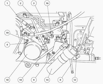
Disconnect and block:
- the hose (1) to the Massey Ferguson 6245, 6260, 6265, 5460, 5465
auxiliary system
- the rear differential lock pipe (2) and the hose (8) from the front
differential lock control (if fitted)
- the 4WD clutch supply pipe (10) for tractors fitted with this option
- the PTO brake supply pipe (3).
- the steering spool valve supply pipe (9) via the 15 micron filter(s)
(14)
- the 20 bar hydraulic cover plate supply pipe.
Disconnect the harness of the engine speed sensor (16) and filter switch
(19).
Disconnect the solenoid valves, marking their connections. The function
of each solenoid valve is indicated on the external face of the
hydraulic cover plate casing.
The cover plate is fitted with two different types of solenoid valves. The solenoid valve (8) of the PTO brake has a solenoid with a diode and
is represented by the
following symbol (+/-).
Remove the screws (4) and the cover plate.
After removing the cover plate, if necessary, remove the transfer pipe
from the housing, ensuring hydraulic continuity to the pump manifold.
Installing
Clean the mating faces of the housing and cover plate.
Check for the presence of the two centring pins and rivets at the ends
of the channels on the cover plate.
Install new seals:
- on the Hare / Tortoise channels
- on the power take-off clutch channel.
Install and position the suction pipe, with its notch along the axis of
the pin. Install the seal.
Screw two makeshift guide studs into opposing holes on the housing.
Install the transfer pipe (if removed), first checking the seals are in
a good condition.
Smear the mating faces of the cover plate with a sealing product
(Loctite 510 or equivalent) taking care not to block the hydraulic ports
of the Hare / Tortoise
mechanism. Reinstall the cover plate. Take out the guide studs. Install
and tighten the screws to 72-96 Nm.
Reconnect (in accordance with the markings made):
- solenoid valves
- filter switch
- engine speed sensor.
Attach the electrical harnesses with a retainer.
Reconnect the pipes and hose. Reinstall the trailer brake spool valve.
Check the condition of the seal of the strainer (18) and lubricate it.
Reinstall the strainer and tighten it an additional quarter turn after
it contacts with the seal.
Reinstall the 15 micron filter(s) and the support. Reconnect the
blockage indicator.
Lift the MF 6245, 6260, 6265, 5460, 5465 tractor. Install the wheel.
Remove the axle stand and tighten the nuts. Remove the chocks.
Top up the tractor transmission oil level of the rear axle and check it
using the gauge located to the rear of the centre housing.
Check the operation of the electrical circuits, the low pressure switch,
the solenoid valves, the filter switch and the blockage indicator.
If the pump has been replaced, or if the disassembly of one or several hydraulic component(s) was necessary, check the hydraulic system by carrying out the relevant tests.
Check the tightness of the cover plate mating face, the strainer and the hydraulic unions.
________________________________________________________________________________
________________________________________________________________________________________
________________________________________________________________________________________
________________________________________________________________________________________
________________________________________________________________________________________
________________________________________________________________________________________
________________________________________________________________________________________
________________________________________________________________________________________
________________________________________________________________________________________
________________________________________________________________________________________
________________________________________________________________________________________
________________________________________________________________________________________
________________________________________________________________________________________
________________________________________________________________________________________
________________________________________________________________________________________
________________________________________________________________________________________
________________________________________________________________________________________
________________________________________________________________________________________
________________________________________________________________________________________
 SPECS
SPECS LOADERS
 MAINTENANCE
 PROBLEMS
 MF 1523
 MF 1531
 MF 135
 MF 1547
 MF 1635
 231
231 231S
231S 235
235 240
240 241
241 255
255 265
265 274
274 285
285 375
375 916X Loader
 921X Loader
 926X Loader
 931X Loader
 936X Loader
 941X Loader
 946X Loader
 951X Loader
 956X Loader
 988 Loader
 1655
1655 GS1705
 1742
1742 2635
2635 4608
4608 1080
1080 1100
1100 2615
2615 3050
3050 3060
3060 4708
4708 5455
5455 5450
5450 5610
5610 5613
5613 DL95 Loader
 DL100 Loader
 DL120 Loader
 DL125 Loader
 DL130 Loader
 DL135 Loader
 DL250 Loader
 DL260 Loader
 L90 Loader
 L100 Loader
 6499
6499 7480
7480 7618
7618 7726
7726 1533
1533 2604H
2604H 2607H
2607H 4455
4455 4610M
4610M 4710
4710 L105E Loader
 L210 Loader
 1014 Loader
 1016 Loader
 1462 Loader
 1525 Loader
 1530 Loader
 232 Loader
 838 Loader
 848 Loader
 5712SL
 6713
6713 6715S
6715S 7475
7475 7615
7615 7716
7716 7724
7724 8240
8240 8650
8650 8732
8732 246 Loader
 1036 Loader
 1038 Loader
 1080 Loader
 856 Loader