
________________________________________________________________________________
Massey Ferguson 6255, 6270, 6170, 6180 - hydraulic system tests
Massey Ferguson 6100-6200 series tractors open centre hydraulic system (57 l/min) comprises two systems: the low flow rate system and the high flow rate system.
Before starting the tests, run the engine at 2000 rpm to raise the oil temperature to 60 °C (132 °F) minimum.
To make the rise in temperature easier, connect a flowmeter to one of the auxiliary spool valves other than the one supplied by the flow divider (if fitted) and limit the flow through the flowmeter.
As soon as the oil temperature reaches or exceeds 60°C (132°F), release
the lever of the auxiliary spool valve and open the flowmeter load valve
to the maximum.
MF 6170, 6180 high flow rate system
Safety valve test - Connect a pressure gauge with a coupler to the
diagnostics connector.
This diagnostics connector is located:
- either on the trailer brake valve (if fitted);
- or on the cover plate (2) fitted to the right-hand hydraulic cover
plate.
- Run the engine at 2200 rpm.
- Activate an auxiliary spool valve to open the valve.
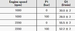
- Check P1 = 195 ± 5 bar.
If pressure P1 is not correct, adjust the safety valve using shim(s) -
At 1000 rpm, the pressure should not drop.
Checking the flow rate of the pump
- Connect a flowmeter to the quick coupling of an Massey Ferguson 6170,
6180 auxiliary spool valve other than the one supplied by the flow
divider. Connect the
return directly to the housing via the transmission filler port.
- Connect a suitable pressure gauge to the diagnostics connector. Check
that the flowmeter load valve is open fully.
- Activate the spool valve.
- Adjust the flowmeter load valve to obtain P1. Do not consider the
value of the pressure gauge fitted to the flowmeter. Look at the
separate pressure gauge
connected to the diagnostics connector.
- Check Q1.
Checking the flow divider (if fitted)
Connect a flowmeter to a quick coupling on auxiliary spool valve no.1
located by the flow divider "D".
Connect the return directly to the housing via the transmission filler
port.
Connect a suitable pressure gauge to the diagnostics connector. Check
that the flowmeter load valve is open fully.
Activate the spool valve. Adjust the flowmeter load valve to obtain P1.
Check the flow rate of the divider by turning the adjusting knob
shown. Check Q2.
Engine speed (rpm) - 2200
P1 (bar) - 0 to 150
Q2 (l/min) - 0 to 53
Do not consider the value of the pressure gauge fitted to the flowmeter.
Look at the separate pressure gauge connected to the diagnostics
connector (1).
Checking Kick-out pressure on an auxiliary spool valve fitted with
automatic return to neutral
Connect a flowmeter to the relevant spool valve.
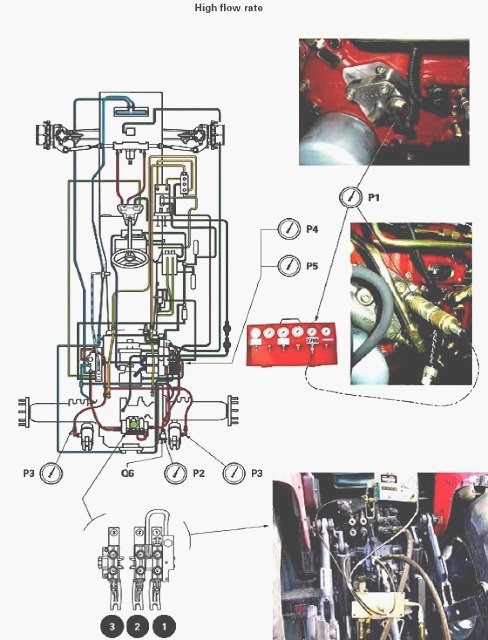
Connect a suitable pressure gauge to the diagnostics connector (1).
Run the engine at 2200 rpm.
Activate the MF 6255, 6270 spool valve in automatic return position.
Release the lever and gradually shut the flowmeter load valve until the
lever returns to neutral position.
Check the Kick-out pressure: P1 = 150 - 170 bar.
Make sure that the spool valve is in the automatic return position and
not in the floating position. Do not consider the value of the pressure
gauge fitted to the
flowmeter. Look at the separate pressure gauge connected to the
connector (1).
Checking the pressure and flow rate of the trailer brake
Pressure
- Connect a pressure gauge to the trailer brake connector.
- Run the engine at 2200 rpm.
- Lock the brake pedals together and apply a progressive force.
The pressure read should increase gradually until it reaches P2 = 130 -
150 bar maximum.
Flow rate
- Connect a flowmeter to the trailer brake connector.
- Connect the return directly to the housing via the transmission filler
port.
- Run the engine at 2200 rpm.
- Activate the coupled brake pedals.
- Check Q6 = 24 - 31 l/min.
Testing the linkage security valve
- Disconnect the supply hose pipes on the rams and connect them to a
manual pump.
- With the engine stopped and the linkage valve in neutral position,
inject pressure into the system.
- Check the valve opening pressure: P3 = 200 - 210 bar.
________________________________________________________________________________
________________________________________________________________________________________
 SPECS
SPECS LOADERS
 MAINTENANCE
 PROBLEMS
________________________________________________________________________________________
 MF 1523
 MF 1531
 MF 135
 MF 1547
 MF 1635
________________________________________________________________________________________
________________________________________________________________________________________
 231
231 231S
231S 235
235 240
240 241
241________________________________________________________________________________________
 255
255 265
265 274
274 285
285 375
375________________________________________________________________________________________
________________________________________________________________________________________
 916X Loader
 921X Loader
 926X Loader
 931X Loader
 936X Loader
________________________________________________________________________________________
 941X Loader
 946X Loader
 951X Loader
 956X Loader
 988 Loader
________________________________________________________________________________________
 1655
1655 GS1705
 1742
1742 2635
2635 4608
4608________________________________________________________________________________________
 1080
1080 1100
1100 2615
2615 3050
3050 3060
3060________________________________________________________________________________________
 4708
4708 5455
5455 5450
5450 5610
5610 5613
5613________________________________________________________________________________________
 DL95 Loader
 DL100 Loader
 DL120 Loader
 DL125 Loader
 DL130 Loader
________________________________________________________________________________________
 DL135 Loader
 DL250 Loader
 DL260 Loader
 L90 Loader
 L100 Loader
________________________________________________________________________________________
 6499
6499 7480
7480 7618
7618 7726
7726 1533
1533________________________________________________________________________________________
 2604H
2604H 2607H
2607H 4455
4455 4610M
4610M 4710
4710________________________________________________________________________________________
 L105E Loader
 L210 Loader
 1014 Loader
 1016 Loader
 1462 Loader
________________________________________________________________________________________
 1525 Loader
 1530 Loader
 232 Loader
 838 Loader
 848 Loader
________________________________________________________________________________________
 5712SL
 6713
6713 6715S
6715S 7475
7475 7615
7615________________________________________________________________________________________
 7716
7716 7724
7724 8240
8240 8650
8650 8732
8732________________________________________________________________________________________
 246 Loader
 1036 Loader
 1038 Loader
 1080 Loader
 856 Loader