________________________________________________________________________________
Massey Ferguson 6290, 6270 transmission - Mechanical reverse shuttle
Massey Ferguson 6290, 6270 tractors may be fitted with a Heavy gearbox featuring a mechanical reverse shuttle.
The reverse shuttle transmits movement commanded at the Dynashift into
the transfer shaft installed at the front of the main gearbox, by the
action of the dual gear.
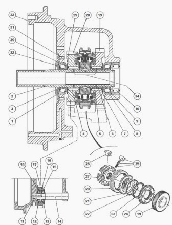
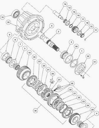
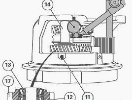
MF 6290, 6270 transmission - Mechanical reverse shuttle
(1) Shim(s) (2) Secondary shaft (3) Bearing cone (4) Needle roller
bearing (5) Needle roller bearing (6) Bush (7) Washer (8) Bearing cone
(9) Bearing cup (10) Roller bearing (11) Screw (12) Bearing cone (13)
Bearing cone (14) Idling gear shaft (15) Bearing cup (16) Spacer ring
(17) Reverse-drive idling gear (18) Bearing cup (19) Forward drive gear
(20) Synchromesh slide (21) Rings (22) Rings (23) Cones (24) Synchromesh
flanges (25) Locking device (26) Shoes (27) Synchromesh hub (28)
Reverse-drive gear (29) Washer (30) Bearing cup (31) Screw (32)
Retaining plate (33) Housing (34) Synchromesh assembly
The reverse shuttle assembly is located in the rear cavity of the input
housing behind the Dynashift.
It includes:
- two helically cut pinions (19) and (28) installed on two needle
bearings (4) and (5). These pinions are respectively in constant
engagement with the dual gear at the
box main input drive and reverse-drive idling gear (17)
- twin-cone synchromesh assembly (34), the hub is locked by the splines
on secondary shaft (2)
- a synchromesh-control selector rail and fork assembly.
- secondary shaft (2) installed on two tapered roller bearings supported
by two bearings in the input housing
- reverse drive idling gear (17) rotating on two tapered roller bearings
installed on shaft (14) mounted in two bores in the housing.
The latter gear is in constant engagement with the front teeth of the
gearbox dual input gear.
When the synchromesh slide is over on the right, it transmits movement
to forward drive gear (19) in direct connection with the rear teeth of
the gearbox dual input
gear.
Reverse drive
Forward-drive gear (28) is in constant engagement with idling gear (17)
which meshes with the front teeth of the gearbox dual input gear.
Split the Massey Ferguson 6270, 6290 tractor between the engine and
gearbox.
Drain the gearbox and the intermediate housing.
Visually identify the contour of the plugs.Remove the hydraulic clutch.
Remove the selector cover.
Remove the input housing.
Disassemble the locking device, the selector rail and the reverse
shuttle fork.
Place the housing on a work bench in the vertical position. Remove the
sling.
Disassemble the Dynashift.
MF 6290, 6270 gearbox reverse shuttle repair
Remove screws (11), extract shaft (14). Remove gear (17) and bearing
cones (12) and (13).
Drive out cups (15) and (18). Remove spacer ring (16).
Pair the cones and cups if they are to be reused.
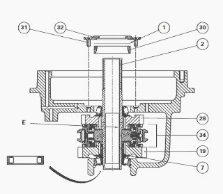
Remove screws (31). Remove retaining plate (32), shims (1) and cup (30).
Extract secondary shaft (2).
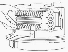
Remove the assembly comprising pinions (19) and (28), synchro (34) and
washer (7).
Remove cone (8) and cup (9).
Separate the following parts on the pinion or synchromesh assembly: gear
(19), bush (6), needle roller bearings (5), cones (23), rings (21),
rings (22), synchromesh
flanges (24), gear (28) and needle roller bearings (4).
If necessary, withdraw cone (3) from the shaft, remove washer (29), and
drive out roller bearing (10).
Clean and check the parts and replace any that are faulty.
Check that the pipes and ports in secondary shaft (2), shaft (14),
housing (33), synchromesh (34) and bush (6) are not blocked.
Ensure that the plug (rivet) is crimped into the housing, on the end of
the lube pipe to the reverse drive idling gear.
If necessary, overhaul synchromesh (34).
If it was removed, refit washer (29) on shaft (2) then fit cone (3) in
abutment on the washer, using a press and a suitable fixture.
Lubricate the shaft, the cones and the bearing cups.
Assemble gear (19) and bush (6) by positioning the inner recess towards
drive hub (27) of the assembly comprising (34), needle roller bearings
(5), cones (23),
rings (21), rings (22), synchromesh flanges (24), gear (28) and needle
roller bearings (4).
Refit the assembly comprising pinions (19) and (28), synchro (34) and
washer (7).
Centre the washer. Insert secondary shaft (2) through the front bore in
the housing, into the pinion / synchro assembly.
Install shaft (2), with shoulder E in contact with the synchromesh hub.
If shimming of the secondary shaft proves to be necessary, otherwise
continue the assembly operation.
Install cup (30), shims (1) and retaining plate (32).
Coat screw (31) with Loctite 241 or equivalent; install and torque to 25
- 32 Nm.
Manually check the axial play and rotation of pinions (19) and (28) and
shaft (2).
If shimming of the reverse-drive idling gear proves to be necessary.
Install idling gear fitted with spacer ring (16), bearing cones
(12) (13) and shaft (14).
Apply a light quantity of Loctite 241 or equivalent to screw (11);
install and torque to 40 - 56 Nm.
Check with fingers for normal backlash of gear (17) and rotation of the
complete gear train.
Install roller bearing (10).
Preparing and shimming the secondary shaft
Position the housing in a vice.
Calculate shim thickness E (1) to obtain a temporary clearance of 0.10
to 0.20 mm maximum.
Position cup (30), shims (1) as calculated earlier, and retaining plate
(32).
Install and provisionally tighten screw (31) without Loctite to 25 - 32
Nm.
Place the feeler of a dial gauge on the extremity of shaft (2).
Exert a hard pull on the shaft, rotating it alternately right and left
in order to correctly seat the cones in the bearing cups.
Adjust the dial gauge pointer to zero.
Depending on the clearance value J obtained, select a new thickness of
shims C (1) to obtain a preload: P1 = 0.10 to 0.20 mm According to the
formula: C = E + J
+ P1.
If possible, set at the top value of the tolerance.
Remove screw (31), remove retaining plate (32).
Install final shims (1) selected at operation 42, on cup (30). Reinstall
the retaining plate. Install and torque screw (31).
Preparing and shimming the reverse drive idling gear
Position the housing in a vice.
Install minimum spacer ring (16) in the groove of gear (17) then fit
cups (15) and (18) in abutment on
the segment.
Position gear (17) and cones (12) and (13) on the housing. Slide shaft
(14).
Install screw (11) without Loctite, and torque to 40-56 Nm.
Adjust shims to obtain a clearance: J2 = 0.05 to 0.18 mm.
Apply the feeler of a dial gauge to gear (17).
Exert a hard push on the gear, alternately rotating to right and left in
order to seat the cones correctly in the cups.
Adjust the dial gauge to zero.
Depending on the value read on the dial gauge, select the definitive
spacer ring (16) to obtain J2.
If necessary, remove gear (17). Drive out cups (15) and (18). Remove
spacer ring (16). Install the spacer ring selected at operation 54.
Install the cups. Reinstall the
gear. Repeat operation 30.
Coat screw (11) with Loctite 241 or equivalent, install and definitively
torque to 40 - 56 Nm.
Check with fingers for normal backlash at gear (17) and rotation of the
gear train.
Reassemble the Dynashift
Reassemble the reverse shuttle fork, the selector rail and the locking
device.
Install the input housing.
Install the selector cover.
Install the hydraulic clutch (pressure loaded).
Reassemble the MF 6270, 6290 tractor between the engine and gearbox.
Service the oil in the sumps and check the level on the sight glass
located on the left of the centre housing.
If necessary, bleed the hydraulically controlled clutch.
Proceed to road test of all Dynashift controls.
Check the leak tightness of the hydraulic connections and the mating face of the selector cover.
________________________________________________________________________________
 SPECS
SPECS LOADERS
 MAINTENANCE
 PROBLEMS
________________________________________________________________________________________
 MF 1523
 MF 1531
 MF 135
 MF 1547
 MF 1635
________________________________________________________________________________________
 231
231 231S
231S 235
235 240
240 241
241________________________________________________________________________________________
 255
255 265
265 274
274 285
285 375
375________________________________________________________________________________________
________________________________________________________________________________________
 916X Loader
 921X Loader
 926X Loader
 931X Loader
 936X Loader
________________________________________________________________________________________
 941X Loader
 946X Loader
 951X Loader
 956X Loader
 988 Loader
________________________________________________________________________________________
 1655
1655 GS1705
 1742
1742 2635
2635 4608
4608________________________________________________________________________________________
 1080
1080 1100
1100 2615
2615 3050
3050 3060
3060________________________________________________________________________________________
 4708
4708 5455
5455 5450
5450 5610
5610 5613
5613________________________________________________________________________________________
 DL95 Loader
 DL100 Loader
 DL120 Loader
 DL125 Loader
 DL130 Loader
________________________________________________________________________________________
 DL135 Loader
 DL250 Loader
 DL260 Loader
 L90 Loader
 L100 Loader
________________________________________________________________________________________
 6499
6499 7480
7480 7618
7618 7726
7726 1533
1533________________________________________________________________________________________
 2604H
2604H 2607H
2607H 4455
4455 4610M
4610M 4710
4710________________________________________________________________________________________
 L105E Loader
 L210 Loader
 1014 Loader
 1016 Loader
 1462 Loader
________________________________________________________________________________________
 1525 Loader
 1530 Loader
 232 Loader
 838 Loader
 848 Loader
________________________________________________________________________________________
 5712SL
 6713
6713 6715S
6715S 7475
7475 7615
7615________________________________________________________________________________________
 7716
7716 7724
7724 8240
8240 8650
8650 8732
8732________________________________________________________________________________________
 246 Loader
 1036 Loader
 1038 Loader
 1080 Loader
 856 Loader