
________________________________________________________________________________
Massey Ferguson 6485, 6490 Dyna 6 Transmission construction
Powershift module and Power-Shuttle
Massey Ferguson 6490, 6485 Dyna 6 transmission Powershift module is
fitted behind the engine flywheel.
The Powershift module comprises:
- the multiplier module;
- the Dynashift module.
Each module is fitted in a cast-iron housing screwed into the front
gearbox housing.
Multiplier module
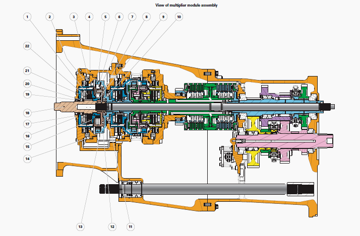
MF 6485, 6490 Dyna 6 Transmission Multiplier module
(1) Clutch Q disc/intermediate plate assembly, (2) Brake P
disc/intermediate plate assembly, (3) Spring, (4) Multiplier module
housing, (5) Ring gear, (6) Planetary
gear, (7) Needle bearing, (8) Pin, (9) Sun gear, (10) Ball bearing, (11)
Ball bearing, (12) Ring-gear carrier, (13) Planet carrier, (14) Brake
piston, (15) Clutch cover,
(16) Friction washers, (17) Cover, (18) Input shaft, (19) Lip seal, (20)
Ball bearing, (21) Clutch bell housing, (22) Belleville washers
The multiplier module comprises an epicyclic gear train, a clutch and a
brake.
The input shaft (18) is linked to the planet carrier (13). It drives the
power take-off shaft via the vibration damper located in the engine
flywheel.
The clutch discs (1) are splined to the input shaft (18). The
intermediate plates of the clutch (1) are integral with the clutch bell
housing (21) and sun gear (9).
The brake discs (2) are connected to the clutch bell housing (21) and
sun gear (9).
The ring gear (5) and ring gear carrier (12) of the epicyclic gear train
drive the primary shaft of the Dynashift module.
Dynashift module
The Dynashift module comprises two epicyclic gear trains (primary and
secondary), two brakes and two clutches.
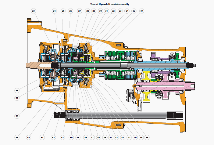
MF 6490, 6485 Dyna 6 Transmission Dynashift module
(23) Thrust plate, (24) Friction washer, (25) Clutch bell housing, (26)
Brake piston, (27) Ball bearing, (28) Needle bearing, (29) Secondary
planet carrier, (30) Brake
piston, (31) Pin, (32) Spring, (33) Needle bearing, (34) Brake N
disc/intermediate plate assembly, (35) Clutch bell housing, (37)
Friction washer, (38) Belleville
washers, (39) Clutch O disc/intermediate plate assembly, (40) Rear
cover, (41) Ball bearing, (42) Secondary sun gear, (43) Pin, (44)
Planetary gear, (45)
Secondary ring gear, (46) Secondary ring-gear carrier, (47) Ball
bearing, (48) Primary sun gear, (49) Planetary gear, (50) Primary ring
gear, (51) Primary ring-gear
carrier, (52) Primary planet carrier, (53) Dynashift module housing,
(54) Spring emplacement, (55) Brake L disc/intermediate plate assembly,
(56) Clutch M
disc / intermediate plate assembly, (57) Belleville washers, (58) Primary
shaft
Primary epicyclic gear train
The ring gear (50) of the primary gear train is splined to the primary
shaft (58). It rotates at the multiplier secondary speed.
The planet-carrier (52), linked to the shaft/Power-Shuttle bell
housings, supplies output rotational speed to the Dynashift module.
The sun gear (48) on the primary epicyclic gear train is connected to
the planet-carrier (29) on the secondary epicyclic gear train.
Secondary epicyclic gear train
The secondary gear train (45) ring gear can be locked in rotation by the
brake (55) or fixed to the primary shaft (58) by the multidisc clutch
(56).
The secondary sun gear (42) can be locked in rotation by the brake (34)
or fixed to the shaft/PowerShuttle bell housings by the multidisc clutch
(39).
The secondary planet-carrier (29) is fixed to the sun gear (48) on the
primary epicyclic gear train.
Clutch/brake operation
The clutches/brakes that select the Massey Ferguson 6485, 6490 Dyna 6
Dynashift module ratios are each controlled by a piston.
When a brake is engaged, the related clutch is disengaged, and vice
versa.
The control pistons act both on the brake discs and on an intermediate
plate.
When the piston is pressurised, the plate pushes back the Belleville
washers of the clutch.
When the pressure is released, the Belleville washers push the piston
back via the intermediate plate and tighten the clutch discs.
PowerShuttle: reverse
Reverse is provided by a mainshaft comprising a shaft and two pinions.
It transmits drive from the PowerShuttle to the 2nd gear pinion on the
main unit output shaft.
The pinions are splined to the shaft.
The pinion is mounted on different size taper roller bearings, shimmed
with preload under the bearing cup.
Main gearbox construction
The main gearbox is crossed entirely by the power take-off shaft (116)
which links the engine flywheel to the power take-off clutch at the
front of the rear axle. This
shaft turns at the centre of a series of shafts forming the upper
shaftline.
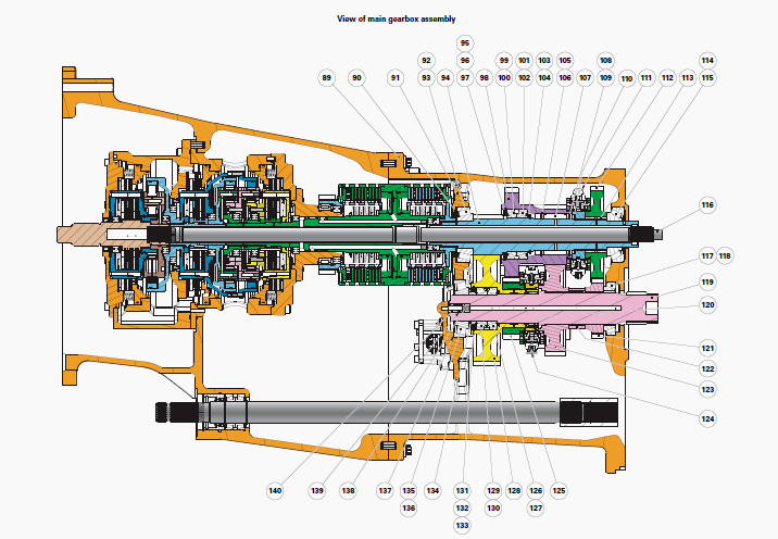
Main gearbox
(89) Gearbox housing, (90) Shim(s), (91) Compartment, (92) Bearing cup,
(93) Bearing cone, (94) Primary shaft, (95) Circlip, (96) Thrust washer,
(97) Shim(s), (98)
1st/3rd double pinion, (99) Bearing cup, (100) Bearing cone, (101)
Bearing cone, (102) Bearing cup, (103) Spacer, (104) Circlip, (105)
Circlip, (106) Thrust washer,
(107) Needle bearing, (108) Thrust washer, (109) Circlip, (110) Special
circlip, (111) 3rd/4th double cone synchroniser, (112) 4th driving gear,
(113) Ring, (114)
Bearing cup, (115) Bearing cone, (116) Power take-off shaft, (117)
Bearing cone, (118) Bearing cup, (119) Output shaft, (120) Needle
bearing, (121) 4th driven
pinion, (122) Spacer, (123) 3rd driven pinion, (124) 1st/2nd double cone
synchroniser, (125) 1st driving gear, (126) Bearing cone, (127) Bearing
cup, (128) 2nd gear
pinion, (129) Bearing cup, (130) Bearing cone, (131) Circlip, (132)
Thrust washer, (133) Shim(s), (134) Special spacer, (135) Bearing cup,
(136) Bearing cone, (137)
Shim(s), (138) Spring, (139) "O" ring, (140) Lubrication pipe
A vertical compartment (91) in front of the main gearbox housing (89)
supports the front bearings (92)(93) and (135)(136) on the primary (94)
and output (119)
shafts. It is also fitted with the lubricating channels.
The main
gearbox front and rear housings are bolted together and act as an oil
tank for the MF 6485, 6490 tractor
hydraulic circuit.
The main gearbox has four synchronised ratios with two double cone
synchronisers. Four gear trains are divided between two shafts (94)
(119). Each range is
engaged via a synchroniser.
A safety finger on the selection mechanism
prevents two ranges being engaged simultaneously. The first ratio uses
three gear trains.
The last three ratios each use one gear train (see kinematics).
Primary shaft
The primary shaft (94) is supported by two taper roller bearings
(92)(93) and (114)(115). It is preloaded under the bearing cup (92)
using the shims (90).
On the primary shaft (94), the double 1st/3rd gear pinion (98) forms a
single unit supported by:
- two taper roller bearings (99)(100) and (101)(102) fitted in an X
shape;
- a needle bearing (107).
The position of the double pinion should be checked (98) in relation to
the special circlip (110), so that the 3rd/4th gear double cone
synchroniser (111) synchronises
range 3 correctly.
The taper roller bearings (99)(100) and (101)(102) are shimmed with a
slight clearance or a slight preload using the shims (97).
The machined
teeth on the primary
shaft (94) mesh constantly with the 2nd driven pinion (128) on the
output shaft (119). The 4th gear pinion (112) turns freely on a ring
(113) fitted with a lubricating
port.
Output shaft
The primary shaft (119) is supported by two taper roller bearings
(117)(118) and (135)(136). It is preloaded under the bearing cup (135)
using the shims (137).
The 2nd gear driven pinion (128) turns freely on the output shaft (119).
It is supported by:
- two taper roller bearings (126)(127) and (129)(130) fitted in an X
shape;
- a needle bearing (120).
The taper roller bearings (126)(127) and (129)(130) are shimmed with a
slight clearance or a slight preload using the shims (133).
The 2nd gear driven pinion (128) acts as a rotating axis for the 1st driving gear (125), which turns without a bearing thanks to a consequential, specific heat treatment.
The friction surface is lubricated through radial ports. The 1st/2nd gear double cone synchroniser (124) is splined to the 2nd gear driven pinion (128).
It attaches this to the pinions (125) or (123) according to the range engaged. The 3rd (123) and 4th (121) gear driven pinions are splined to the output shaft (119).
________________________________________________________________________________
________________________________________________________________________________________
 SPECS
SPECS LOADERS
 MAINTENANCE
 PROBLEMS
________________________________________________________________________________________
 MF 1523
 MF 1531
 MF 135
 MF 1547
 MF 1635
________________________________________________________________________________________
________________________________________________________________________________________
 231
231 231S
231S 235
235 240
240 241
241________________________________________________________________________________________
 255
255 265
265 274
274 285
285 375
375________________________________________________________________________________________
________________________________________________________________________________________
 916X Loader
 921X Loader
 926X Loader
 931X Loader
 936X Loader
________________________________________________________________________________________
 941X Loader
 946X Loader
 951X Loader
 956X Loader
 988 Loader
________________________________________________________________________________________
 1655
1655 GS1705
 1742
1742 2635
2635 4608
4608________________________________________________________________________________________
 1080
1080 1100
1100 2615
2615 3050
3050 3060
3060________________________________________________________________________________________
 4708
4708 5455
5455 5450
5450 5610
5610 5613
5613________________________________________________________________________________________
 DL95 Loader
 DL100 Loader
 DL120 Loader
 DL125 Loader
 DL130 Loader
________________________________________________________________________________________
 DL135 Loader
 DL250 Loader
 DL260 Loader
 L90 Loader
 L100 Loader
________________________________________________________________________________________
 6499
6499 7480
7480 7618
7618 7726
7726 1533
1533________________________________________________________________________________________
 2604H
2604H 2607H
2607H 4455
4455 4610M
4610M 4710
4710________________________________________________________________________________________
 L105E Loader
 L210 Loader
 1014 Loader
 1016 Loader
 1462 Loader
________________________________________________________________________________________
 1525 Loader
 1530 Loader
 232 Loader
 838 Loader
 848 Loader
________________________________________________________________________________________
 5712SL
 6713
6713 6715S
6715S 7475
7475 7615
7615________________________________________________________________________________________
 7716
7716 7724
7724 8240
8240 8650
8650 8732
8732________________________________________________________________________________________
 246 Loader
 1036 Loader
 1038 Loader
 1080 Loader
 856 Loader