
________________________________________________________________________________
Massey Ferguson 6465, 6475 gearbox - Creeper unit
The Massey Ferguson 6475, 6465 creeper speed reducer consists of an epicyclic gear train with a planet carrier and ring gear assembly fitted at the rear of the main gearbox.
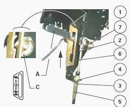
It is controlled by a lever located on the cab console and linked by a cable to a rod fitted on the front right-hand side of the centre housing. This rod moves the coupler control fork.
Creeper gears can only be selected if the main gearbox is in the Tortoise range. The coupler (8) is splined to the connecting shaft (21).
Moving the lever "A" to Snail position moves the coupler (8) back and engages it with the planet carrier (1) via its external teeth. The speed of the shaft (21) is 1/4 in relation to the output shaft.
For normal gears, the gearbox output shaft is attached to the connecting
shaft (21) when the coupler (8) is moved forward, thus ensuring direct
drive. When the creeper range is selected, the Snail indicator light on
the instrument panel comes on.
When the Hare range indicator light flashes, this indicates to the
operator that Hare position is engaged and shifting to Tortoise position
is required.
The electrical signal corresponding to selection of the creeper range is
transmitted via switch "C", which is fitted on the control unit.
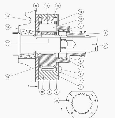
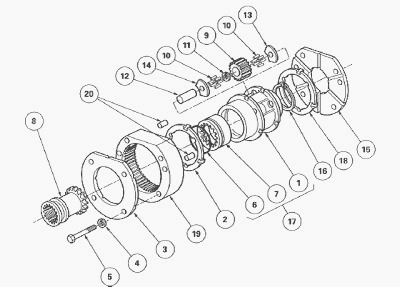
(1) Planet carrier (2) Friction washer (3) Cover plate (4) Lock washer
(5) Screw (6) Snap ring (7) Coupler ring (8) Sleeve (9) Planet gears
(10) Needle rollers (11) Spacer (12) Pin (13) Gear plate (14) Gear plate
(15) Stop plate (16) Circlip (17) Planet carrier assembly (18) Friction
washer (19) Ring gear (20) Centring pin (21) Link shaft
Removing the unit and the ring gear
Take off the MF 6465, 6475 right-hand hydraulic cover plate and, if
required, the left-hand hydraulic cover plate.
Disassemble the PTO assembly.
2-speed PTO - Remove:
- the PTO top cover plate located at the rear of the centre housing;
- the driving gear;
- the intermediate shaft;
- the PTO clutch.
4-speed economy PTO - Remove:
- the PTO top cover plate located at the rear of the centre housing;
- the driving gear;
- the intermediate shaft;
- the MF 6475, 6465 PTO clutch.
Disassemble the sleeve / connecting shaft / coupler / assembly and the
fork.
Removing the unit and the reducer ring gear
Remove the screws (5) and the washers (4)
Remove the cover plate (3).
Take out the planet carrier assembly (17) and the friction washers (2)
(18).
Remove the ring gear (19). The centring pins (20) remain in the ring
gear.
Remove the stop plate (15) without pulling on the output shaft.
Disassembling the planet carrier
Remove the circlip (16).
Drive out the pins (12).
Remove the gear plates (13) (14).
Remove the planet gears (9). Replace the planet carrier (1) if the
coupler ring (7) is damaged.
Reassembling the planet carrier, refitting the ring gear and the unit
Check and clean all components. Replace those that are defective.
Install the planet gears (9). Use miscible grease in oil to fit the
needle rollers (10).
Install the gear plates (13) (14).
Install the pins (12), directing them as required to fit the circlip
(16).
Install the circlip (16). Manually check the axial clearance and
rotation of each planet gear.
Position the stop plate (15) and the ring gear (19) on the housing.
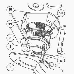
Install the friction washers (2) and (18) smeared with miscible grease
on the planet carrier (1).
Slide the planet carrier onto the output shaft.
Position the cover plate (3). Tighten screws (5) to a torque of 34 - 52
Nm.
Reassemble the fork and the rear sleeve / connecting shaft / coupler
assembly.
Reassemble the Massey Ferguson 6465, 6475 PTO assembly.
2-speed PTO
- Install the power take-off clutch.
- Install the intermediate shaft, the driving gear and the PTO top cover
plate.
4-speed PTO
- Install the power take-off clutch.
- Install the intermediate shaft, the driving gear and the PTO top cover
plate.
Install the left-hand hydraulic cover plate (if removed) and the
right-hand hydraulic cover plate.
Carry out a road test of the creeper unit.
Check PTO and PTO brake operation.
Adjusting the control
Place control lever A in the Snail position. The control lever may be
located in two positions on the right-hand console, depending on whether
or not an auto-hitch is
fitted.

Screw the clevis (1) level with the end of the threaded part of the
cable (6).
Install the clevis (1) onto lever A with the clip (7). Tighten the nut
(2). Screw the nut (3) on the sheath end (5).
Install the sheath end and the Grower washer on the support. Tighten the
nut (4). Check that the cable is not pinched.
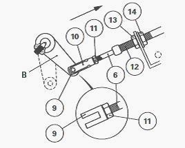
Place connecting rod B in the "creeper" position (reducer dog (8)
engaged towards the rear), fork locked.
Screw the clevis (9) level with the end of the threaded part of the
cable (6).
Install the clevis (9) to rod B using the clip (10). Tighten the nut
(11).
Adjust the stop (12) with the nut (13), making sure that connecting rod
B is still firmly locked.
Tighten the nut (14). After tightening, check that the cable is not
pinched.
Check that the control is locked in the "direct drive" position.
________________________________________________________________________________
________________________________________________________________________________________
 SPECS
SPECS LOADERS
 MAINTENANCE
 PROBLEMS
________________________________________________________________________________________
 MF 1523
 MF 1531
 MF 135
 MF 1547
 MF 1635
________________________________________________________________________________________
________________________________________________________________________________________
 231
231 231S
231S 235
235 240
240 241
241________________________________________________________________________________________
 255
255 265
265 274
274 285
285 375
375________________________________________________________________________________________
________________________________________________________________________________________
 916X Loader
 921X Loader
 926X Loader
 931X Loader
 936X Loader
________________________________________________________________________________________
 941X Loader
 946X Loader
 951X Loader
 956X Loader
 988 Loader
________________________________________________________________________________________
 1655
1655 GS1705
 1742
1742 2635
2635 4608
4608________________________________________________________________________________________
 1080
1080 1100
1100 2615
2615 3050
3050 3060
3060________________________________________________________________________________________
 4708
4708 5455
5455 5450
5450 5610
5610 5613
5613________________________________________________________________________________________
 DL95 Loader
 DL100 Loader
 DL120 Loader
 DL125 Loader
 DL130 Loader
________________________________________________________________________________________
 DL135 Loader
 DL250 Loader
 DL260 Loader
 L90 Loader
 L100 Loader
________________________________________________________________________________________
 6499
6499 7480
7480 7618
7618 7726
7726 1533
1533________________________________________________________________________________________
 2604H
2604H 2607H
2607H 4455
4455 4610M
4610M 4710
4710________________________________________________________________________________________
 L105E Loader
 L210 Loader
 1014 Loader
 1016 Loader
 1462 Loader
________________________________________________________________________________________
 1525 Loader
 1530 Loader
 232 Loader
 838 Loader
 848 Loader
________________________________________________________________________________________
 5712SL
 6713
6713 6715S
6715S 7475
7475 7615
7615________________________________________________________________________________________
 7716
7716 7724
7724 8240
8240 8650
8650 8732
8732________________________________________________________________________________________
 246 Loader
 1036 Loader
 1038 Loader
 1080 Loader
 856 Loader