
________________________________________________________________________________
Massey Ferguson 6480,6490 gearbox - PowerShuttle control unit
The unit fixed to the right-hand side and front of the Massey Ferguson
6490, 6480 gearbox carries out two hydraulic functions quite separate to
the input unit.
It controls:
- the power shuttle,
- the Dynashift.
The channels and ducts machined in the unit allow oil under pressure to
be directed to the reverse shuttle proportional solenoid valves and the
Dynashift solenoid
valves EV1 and EV2.
All solenoid valves are controlled respectively by
the MF 6480, 6490 tractor electronic system. A 60 micron filter element
(8) is located under
the right-hand hydraulic cover, upstream from the control unit. This
additional filter supplies clean oil to the spool of each solenoid
valve.
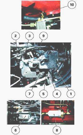
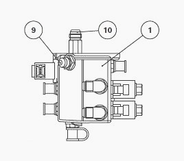
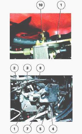
Control unit and hydraulic lines
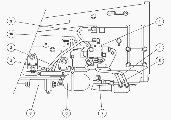
(1) Control unit (2) Return to reverse clutch housing (3) Return to
forward clutch housing (4) Reverse shuttle: 17 bar supply line to
forward clutch (5)
Reverse shuttle: 17 bar supply line to reverse clutch (6) Accumulator
(Nitrogen) (7) Main 17 bar supply line (8) 60 micron filter element (9)
Dynashift: to internal
forward clutch line (17 bar) (10) Dynashift: to internal reverse clutch
line (17 bar)
Massey Ferguson 6480, 6490 Power Shuttle Control
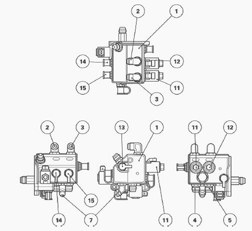
Identification of ports on control unit
(1) Control unit (2) Return to reverse clutch housing (3) Return to
forward clutch housing (4) Pressure outlet to forward clutch (5)
Pressure outlet to reverse clutch
(7) Control unit main supply (17 bar) (13) Control unit pressure
connector (14) Reverse clutch pressure connector (15) Forward clutch
pressure connector
Each of the hydraulic return lines of the proportional solenoid valves
(11) and (12) has separate channels. This design avoids any back
pressure from one solenoid
valve to another.
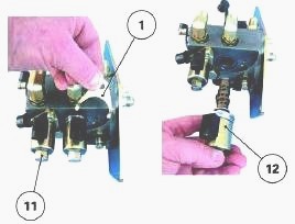
Proportional solenoid valve
Removal
Remove flange (1).
Drive off the solenoid valve (11) or (12) by gently applying pressure
with a screwdriver between the valve and the unit.
Install
Check the condition and cleanliness of the O’rings fitted on the
solenoid valve.
Position and manually drive the solenoid valve into its housing, beyond
the point of resistance (O’rings squeezing).
Position the flange. Tighten the screw from 8 to 11 Nm.
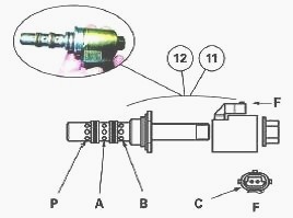
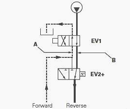
Identification of ports on a proportional solenoid valve
A - Clutch supply ports, B - Clutch return ports, P - 17 bar pressure, C
- Solenoid supply
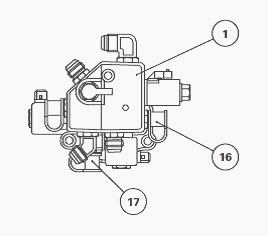
MF 6490, 6480 Dynashift control
Identification of ports on control unit
(1) Control unit (9) Pressure outlet to forward clutch (10) Pressure
outlet to reverse clutch (16) Forward clutch pressure connector (17)
Reverse clutch pressure
connector
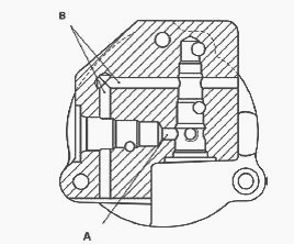
In the control unit, the Dynashift part includes two internal channels A
and B which allow oil to circulate from one solenoid valve to the other.
The four Dynashift
ratios are managed by two solenoid valves.
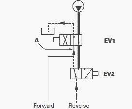
Characteristics of the solenoid valves
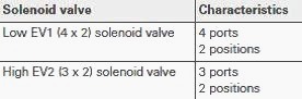
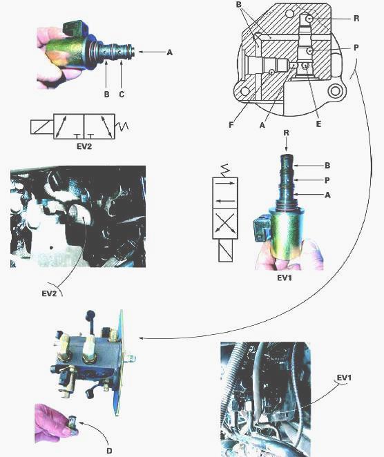
Identification of ports
C - To port F, D - Non-return valve, E - Port to front piston, F - Port
to rear piston, P - 17 bar pressure, R - Return
The removal and install procedure for solenoid valves EV1 and EV2 is the
same as that for a proportional solenoid valve.
Explanation of Dynashift ratios
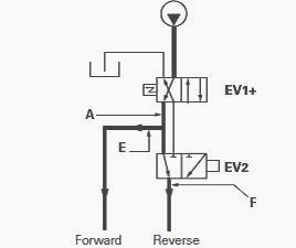
Ratio A
Ratio A is obtained when solenoid valve EV1 is supplied. Oil under
pressure can also reach channel A.
Channel A directs the oil to the front piston via port E and to solenoid
valve EV2.
As this is in neutral position, the oil can pass through the
spool and port F to the
chamber of the rear piston. The two pistons are therefore under
pressure.
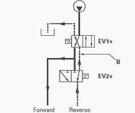
Ratio B
Ratio B is obtained when the two solenoid valves are supplied. Therefore
the flow of oil to the rear piston is interrupted.
The rear piston is
pushed out by springs
which send the oil into channel B. This channel is
joined to the housing by solenoid valve EV1.
Ratio C
Ratio C is obtained by switching off solenoid valve EV1, while
maintaining solenoid valve EV2 under voltage. Channel A is no longer
pressurised but is connected to
the housing.
As a result, the front piston
can return to neutral position. Channel B is under pressure. The oil
flows to the rear piston via solenoid valve EV2.
Ratio D
Ratio D is obtained by switching off EV2. The two solenoid valves are at
rest. The two pistons are connected to the housing via channel A.
Removing and install the control unit
Mark and disconnect the connectors on solenoid valves EV1 and EV2 of the
Dynashift as well as those of the proportional solenoid valves (12) (11)
of the power
shuttle forward and reverse clutches.
Disconnect and remove pipes (2), (3), (4), (5), (7) and (9). To prevent
oil flowing from the gearbox, it is advised to disconnect the return
pipes (2) and (3) at their
higher connections.
Unscrew the support (1) from the MF 6480, 6490 gearbox. Remove the
“support and unit” assembly by gradually unscrewing the union (10)
(Dynashift reverse
clutch supply).
Install the “support and unit” assembly. Tighten:
- the screws fixing the support to the gearbox to 50 - 70 Nm,
- the screws fixing the unit to the support to 25 - 35 Nm.
Reconnect the pipes and connectors.
If it was necessary to replace the control unit or proportional solenoid
valves, test:
- the 17 bar pressure of the unit,
- the Dynashift clutch pressures,
- the pressure of the reverse shuttle forward and reverse clutches.
When pressurised, the reverse shuttle clutches must be calibrated using
Wintest.
Carry out a road test of the hydraulic functions affected by the repair
work.
Check the oil tightness of the hydraulic unions.
________________________________________________________________________________
________________________________________________________________________________________
 SPECS
SPECS LOADERS
 MAINTENANCE
 PROBLEMS
________________________________________________________________________________________
 MF 1523
 MF 1531
 MF 135
 MF 1547
 MF 1635
________________________________________________________________________________________
________________________________________________________________________________________
 231
231 231S
231S 235
235 240
240 241
241________________________________________________________________________________________
 255
255 265
265 274
274 285
285 375
375________________________________________________________________________________________
________________________________________________________________________________________
 916X Loader
 921X Loader
 926X Loader
 931X Loader
 936X Loader
________________________________________________________________________________________
 941X Loader
 946X Loader
 951X Loader
 956X Loader
 988 Loader
________________________________________________________________________________________
 1655
1655 GS1705
 1742
1742 2635
2635 4608
4608________________________________________________________________________________________
 1080
1080 1100
1100 2615
2615 3050
3050 3060
3060________________________________________________________________________________________
 4708
4708 5455
5455 5450
5450 5610
5610 5613
5613________________________________________________________________________________________
 DL95 Loader
 DL100 Loader
 DL120 Loader
 DL125 Loader
 DL130 Loader
________________________________________________________________________________________
 DL135 Loader
 DL250 Loader
 DL260 Loader
 L90 Loader
 L100 Loader
________________________________________________________________________________________
 6499
6499 7480
7480 7618
7618 7726
7726 1533
1533________________________________________________________________________________________
 2604H
2604H 2607H
2607H 4455
4455 4610M
4610M 4710
4710________________________________________________________________________________________
 L105E Loader
 L210 Loader
 1014 Loader
 1016 Loader
 1462 Loader
________________________________________________________________________________________
 1525 Loader
 1530 Loader
 232 Loader
 838 Loader
 848 Loader
________________________________________________________________________________________
 5712SL
 6713
6713 6715S
6715S 7475
7475 7615
7615________________________________________________________________________________________
 7716
7716 7724
7724 8240
8240 8650
8650 8732
8732________________________________________________________________________________________
 246 Loader
 1036 Loader
 1038 Loader
 1080 Loader
 856 Loader