________________________________________________________________________________
Massey Ferguson 6612, 6613 Dyna-4 transmission - powershift module
The Powershift module is fitted on Massey Ferguson 6613, 6612 gearbox (GBA25). It is fitted at the gearbox input and is driven directly by the engine.
This module provides Dyna-4 transmission with four ratios for shifting under load. These four ratios are provided by two epicyclic gear trains, operating with two brakes and two clutches.
The ratios can be controlled with the Power control lever (to the left
under the steering wheel) or with the right-hand armrest lever.
Ratios are shifted in "Speed matching" mode, where the most suitable
ratio for shifting under load is automatically selected when changing
range.
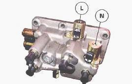
The brakes and clutches are controlled by proportional solenoid valves
(N and L). They are fitted to a hydraulic unit to the front right of the
gearbox that operates on the tractor 20 bar circuit.
Principles of operation
The MF 6612, 6613 tractor gearbox powershift module is made up of two
epicyclic gear trains:
- The front epicyclic gear train, located on the gearbox input. This
comprises a sun gear (36), a planet carrier (25), three planetary gears
(48) and a ring gear (65). It
is controlled by a brake and a clutch. Its ratio is 1.23/1 (speed
multiplied) or 1/1 (train locked).
- The rear epicyclic gear train, located on the gearbox output. This
comprises a sun gear (49), a planet carrier (30), three planetary gears
(50) and a ring gear (29). It
is controlled by a brake and a clutch. Its ratio is 1/1.5 (speed
reduced) or 1/1 (train locked).
Front epicyclic gear train
The input shaft (10) of the module is linked to the planet carrier (25)
of the primary epicyclic gear train.
The sun gear (36) is either attached to the planet carrier (25) (clutch M engaged, epicyclic gear train locked) or to the gearbox housing (brake L engaged, input speed multiplied).
Drive is transmitted
by ring gear (65) to ring
gear (29) of the rear epicyclic gear train.
Rear epicyclic gear train
Input drive is transmitted by the ring gear (29).
The sun gear (49) is either attached to the planet carrier (30) (clutch O engaged, epicyclic gear train locked) or to the gearbox housing (brake N engaged, input speed reduced).
The output shaft
(47) is attached to the planet carrier (30), and is linked to the Power
Shuttle.
Lubrication
The Powershift module is lubricated under pressure by a network of
internal channels.
Oil enters the upper main shaft of the gearbox, then travels through radial bores to the elements to lubricate.
The oil flows from the tractor
hydraulic circuit.
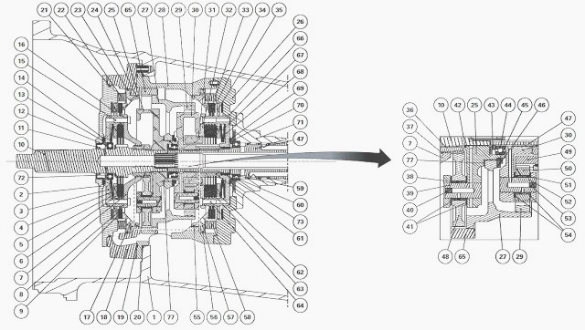
MF 6612, 6613 Dyna-4 transmission powershift module
(1) Housing (2) Cover (3) Clutch M housing (4) Belleville washer (5)
Discs (6) Thrust plates (7) Clutch M cover (8) Discs (9) Thrust plate
(10) Input shaft (11) Lip
seal (12) Ball bearing (13) Friction washer (14) Friction washer (15)
Screws (16) Clutch M/brake L junction plate (17) Brake L piston (18)
Powershift module front
housing (19) "O" ring (20) "O" ring (21) "O" ring
(22) Spring (23) "O" ring (24) "O" ring (25) Front planet carrier (26)
Cover (27) Ring gear carrier (28) Rear housing (29) Rear ring gear (30)
Rear planet carrier (31)
Snap ring (32) Clutch O cover (33) Discs (34) Thrust plates (35) Clutch
O/brake N junction plate (36) Sun gear (37) Snap ring (38) Needle
bearing (39) Pin (40) Plug
(41) Friction washers (42) Snap ring (43) Bronze spacer
(44) Ball bearing (45) Spacer (46) Circlip (47) Output shaft (48)
Planetary gear (49) Sun gear (50) Planetary gear (51) Needle bearing
(52) Pin (53) Plug (54) Friction
washers (55) "O" ring (56) "O" ring (57) Brake N piston (58) Spring (59)
Snap ring (60) Ball bearing (61) Clutch hub
(62) Thrust plates (63) Discs (64) Screws (65) Front ring gear (66)
Clutch O housing (67) Belleville washer (68) Belleville washer (69)
Friction washer (70) Spacer
(71) Bearing (72) Spring washer (73) Needle bearing (74) "O" ring (75)
"O" ring (76) "O" ring (77) Washer
Kinematics
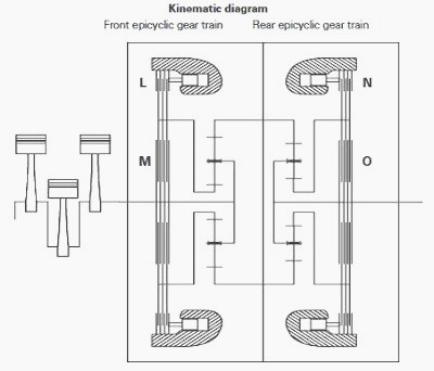
(Av) Forward clutch, (Ar) Reverse clutch, (L) Sun gear brake, front
epicyclic gear train of Powershift module, (M) Sun gear clutch, front
epicyclic gear train of
Powershift module, (N) Sun gear brake, rear epicyclic gear train of
Powershift module, (O) Sun gear clutch, rear epicyclic gear train of
Powershift module
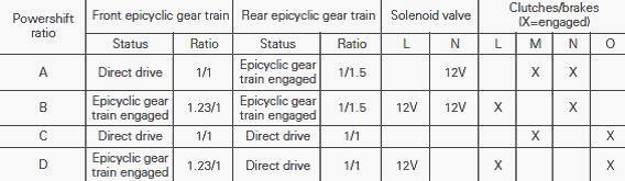
Logic of the ratios
The four ratios are obtained by combining the two epicyclic gear trains.
The front epicyclic gear train multiplies the input speed to 1.23/1,
while the rear epicyclic gear
train reduces the speed to 1/1.5.
Each epicyclic gear train may be
engaged (multiplication or reduction) or locked (ratio 1/1). The two
epicyclic gear trains are used
in combination to obtain the four ratios A, B, C and D.
Clutch / brake operation
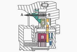
The brakes and clutches operate as a 1 brake/1 clutch set. The brakes
(F) mesh an element to the housing (fixed), and the clutches (E) mesh
two elements in
rotation.
The Massey Ferguson 6612, 6613 tractor clutches/brakes are controlled by a single piston (P).
A junction plate (L) allows the clutch to be released when the brake is engaged, and vice versa. When there is no pressure on the piston (position A), the Belleville washer (R) engages the clutch (E).
When the piston (P) is
actuated (position B), it engages the brake (F) and pushes back the
Belleville washer (R) via the plate (L).
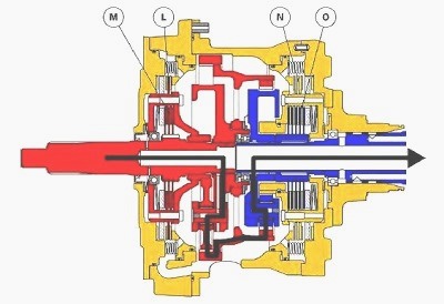
Ratio A (1/1.5)
Brake piston "L" is not pressurised, clutch "M" is engaged and locks the
front epicyclic gear train. Brake piston "N" is pressurised.
The sun
gear of the rear epicyclic
gear train is held in relation to the gearbox housing, enabling the rear
epicyclic gear train to reduce the input speed.
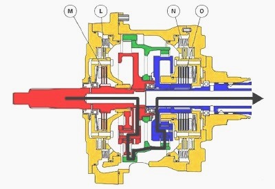
Ratio B (1/1.22)
The two brake pistons L and N are pressurised. The sun gears are held in
relation to the MF 6613, 6612 gearbox housing. The two epicyclic gear
trains are
engaged.
The front epicyclic gear train increases the input speed to
1.23/1 and the rear epicyclic gear train reduces the speed to 1/1.5,
giving an overall ratio of
1/1.22.
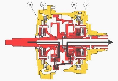
Ratio C (1/1)
None of the pistons is pressurised, clutches "M" and "O" are engaged by
their respective Belleville washers.
Both epicyclic gear trains are
locked and the input
speed is identical to the output speed.
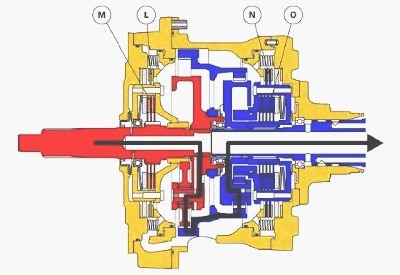
Ratio D (1.23/1)
Brake piston "L" is pressurised, it holds the sun gear of the front
epicyclic gear train in relation to the housing.
The front epicyclic gear train multiplies the input speed to 1.23/1.
Brake piston N is not pressurised. Clutch "O" locks the rear epicyclic gear train; its ratio is 1/1.
________________________________________________________________________________
 SPECS
 LOADERS
 MAINTENANCE
 PROBLEMS
________________________________________________________________________________________
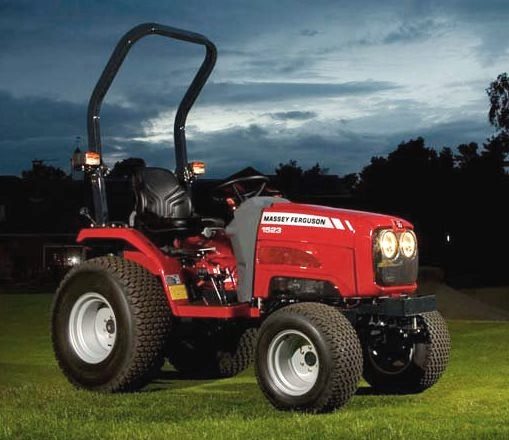 MF 1523
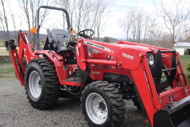 MF 1531
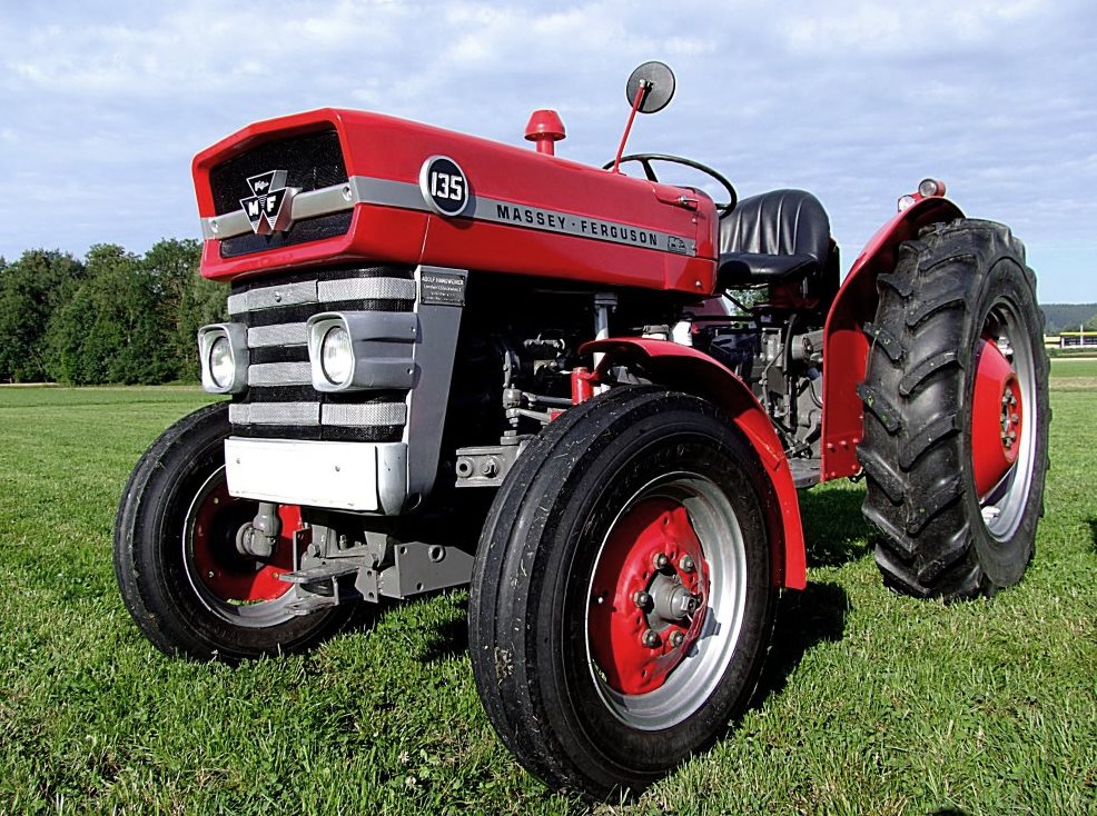 MF 135
 MF 1547
 MF 1635
________________________________________________________________________________________
 231
 231S
 235
 240
 241
________________________________________________________________________________________
_______________________________________________________________________________________
 255
 265
 274
 285
 375
________________________________________________________________________________________
________________________________________________________________________________________
 916X Loader
 921X Loader
 926X Loader
 931X Loader
 936X Loader
________________________________________________________________________________________
 941X Loader
 946X Loader
 951X Loader
 956X Loader
 988 Loader
________________________________________________________________________________________
 1655
 GS1705
 1742
 2635
 4608
________________________________________________________________________________________
 1080
 1100
 2615
 3050
 3060
________________________________________________________________________________________
 4708
 5455
 5450
 5610
 5613
________________________________________________________________________________________
 DL95 Loader
 DL100 Loader
 DL120 Loader
 DL125 Loader
 DL130 Loader
________________________________________________________________________________________
 DL135 Loader
 DL250 Loader
 DL260 Loader
 L90 Loader
 L100 Loader
________________________________________________________________________________________
 6499
 7480
 7618
 7726
 1533
________________________________________________________________________________________
 2604H
 2607H
 4455
 4610M
 4710
________________________________________________________________________________________
 L105E Loader
 L210 Loader
 1014 Loader
 1016 Loader
 1462 Loader
________________________________________________________________________________________
 1525 Loader
 1530 Loader
 232 Loader
 838 Loader
 848 Loader
________________________________________________________________________________________
 5712SL
 6713
 6715S
 7475
 7615
________________________________________________________________________________________
 7716
 7724
 8240
 8650
 8732
________________________________________________________________________________________
 246 Loader
 1036 Loader
 1038 Loader
 1080 Loader
 856 Loader