
________________________________________________________________________________
Massey Ferguson 7499, 7495 load sending auxiliary mechanical spool valves
Massey Ferguson 7495, 7499 tractor proportional auxiliary spool valves, of the Bosch/Rexroth SB23 LS type, are fitted to the high flow rate high pressure circuit.
They are fed by the oil coming from the priority block(s). When no
functions are being activated, the entire flow rate is directed towards
the spool valves.
If certain priority functions are being supplied, the remaining flow is
then available for the auxiliary spool valves. E
ach spool valve has a flow regulating system controlled by a black, red,
green or yellow button located directly on the each spool valve
regulating valve system.
The main spool of the valve is controlled by a cable linked to a lever
in the cab. The spool directs oil towards either outlet port.
Each outlet port is linked to the LS pilot line of the variable
displacement pump regulating valve via the priority block(s).
The auxiliary spool valves are made up of elements themselves containing
spools and valves. Some elements cannot be identified as spare parts.
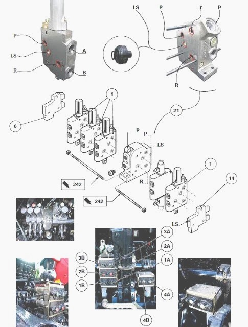
Different types of MF 7499, 7495 spool valve
block components
A spool valve block can consist of three, four or five of the following
components. It can combine components of similar type of or different
types.
Component b
4-position component with flow rate regulation, double acting and
automatic return to neutral.
Component c
4-position component with flow rate regulation, double acting, zero leak
and automatic return to neutral.
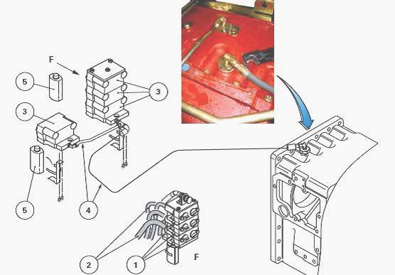
Couplers
The quick-disconnect couplings are held by a bracket on the centre
housing. They are sealed by covers of different colours (red, green,
black or yellow)
corresponding respectively to hydraulic ports A and B of auxiliary spool
valves.
When the auxiliary spool valve is at rest, a lever system (1) allows
existing pressure to be relieved into the hydraulic hoses (2). These
hoses link the spool valves
with the concerned couplers (3).
By acting on this system, the clean oil under pressure is directed to
the return via a hose and pipe assembly (4) connected to the upper part
of the intermediate
housing. This drop in pressure facilitates the connecting of the male
coupler to the female coupler.
The contaminated oil, coming from the separation of the couplers, flows
into flexible and transparent tanks (5) located on either side of the
third-point linkage.
Operation
When the lever in the cab is pulled (spool (1) pushed), the oil enters
via channel P and travels towards the restrictor of the flow regulation
control spool (5) and
grooves of the main spool (1).
The oil is then carried towards a main channel and lifts the ball of
valve (2) to enter a chamber. Displacement of the spool (1)
simultaneously opens the one-way
valve (3).
The oil flows from the chamber towards port A and returns to the housing
through port B via the hydraulic slave device.
The operating principle is identical when the lever is pushed (spool (1)
pulled). The oil flows from the chamber towards port B and returns to
the housing through port
A via the hydraulic slave device.
Layout of components and identification of ports
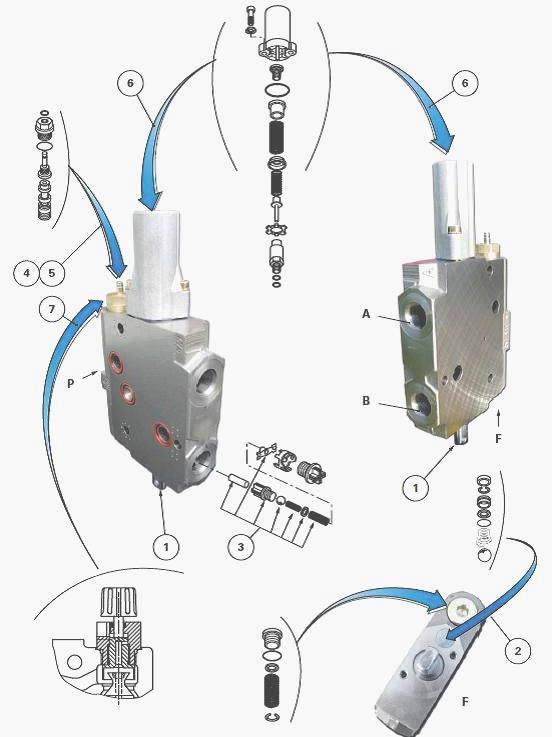
(1) Main spool (2) Valve (3) Non-return valve (4) Flow regulation
control rod (5) Flow regulation control spool (6) Housing and locking
system (7) Flow regulation
control button
Removing and install the spool valve blocks
Disconnect the control cables (7) of each spool valve component by
uncoupling the sleeves (1) located under the cab.
Mark the position of the hydraulics hoses connected to the couplers.
Disconnect them from the MF 7499, 7495 spool valve block.
Disconnect:
- the high pressure pipe;
- the lift ram supply pipes;
- the LS hose.
Mark and disconnect the lift control valve solenoid valve harness (R10
Down - R11 Up).
Removal
Remove the screws and flanges from the manifold.
Sling the MF 7495, 7499 spool valve block.
Separate it from the support. Place it in a clean work area.
If necessary, remove support.
Discard the O'ring.
Reinstall
If it was necessary to remove the support, replace the return pipe
O’rings. Tighten the screws.
Clean the manifold mating face, along with that of the support.
If the studs need replacing, lightly smear the short thread of the new
studs with Loctite 270 or equivalent. Install and tighten the studs.
Clean off any excess Loctite.
Replace the O’ring.
Reinstall the spool valve block on the support.
Tighten:
- the screws to a torque of 50 - 70 Nm;
- the nuts to a torque of 90 - 120 Nm.
Assembling and adjusting a control cable
To be performed on the console
Remove right-hand console cover.
Install the unit (1) and its control cable on the suitable fixture.
Install the console cover.
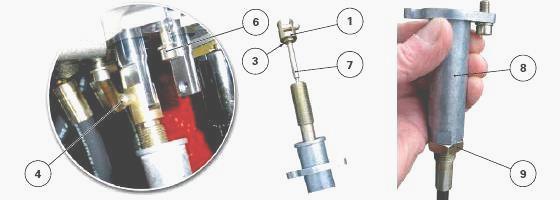
To be performed on the Massey Ferguson 7499, 7495 auxiliary spool valve
Check, without turning, that the valve spool is in neutral position.
Screw clevis (1) flush with the threaded part of cable (7). Tighten nut
(3). Fit the pin (4).
Screw:
- the bell housing (8), partially;
- the screws (6) without tightening them.
Adjust the bell housing (8) by turning it from left to right to centre
the lever (1) in the console opening.
Lock the screws (6). Tighten the nut (9) to a torque of 20 Nm.
Check the operation of the spool valve control in all four positions.
________________________________________________________________________________
________________________________________________________________________________________
 SPECS
SPECS LOADERS
 MAINTENANCE
 PROBLEMS
________________________________________________________________________________________
 MF 1523
 MF 1531
 MF 135
 MF 1547
 MF 1635
________________________________________________________________________________________
________________________________________________________________________________________
 231
231 231S
231S 235
235 240
240 241
241________________________________________________________________________________________
 255
255 265
265 274
274 285
285 375
375________________________________________________________________________________________
________________________________________________________________________________________
 916X Loader
 921X Loader
 926X Loader
 931X Loader
 936X Loader
________________________________________________________________________________________
 941X Loader
 946X Loader
 951X Loader
 956X Loader
 988 Loader
________________________________________________________________________________________
 1655
1655 GS1705
 1742
1742 2635
2635 4608
4608________________________________________________________________________________________
 1080
1080 1100
1100 2615
2615 3050
3050 3060
3060________________________________________________________________________________________
 4708
4708 5455
5455 5450
5450 5610
5610 5613
5613________________________________________________________________________________________
 DL95 Loader
 DL100 Loader
 DL120 Loader
 DL125 Loader
 DL130 Loader
________________________________________________________________________________________
 DL135 Loader
 DL250 Loader
 DL260 Loader
 L90 Loader
 L100 Loader
________________________________________________________________________________________
 6499
6499 7480
7480 7618
7618 7726
7726 1533
1533________________________________________________________________________________________
 2604H
2604H 2607H
2607H 4455
4455 4610M
4610M 4710
4710________________________________________________________________________________________
 L105E Loader
 L210 Loader
 1014 Loader
 1016 Loader
 1462 Loader
________________________________________________________________________________________
 1525 Loader
 1530 Loader
 232 Loader
 838 Loader
 848 Loader
________________________________________________________________________________________
 5712SL
 6713
6713 6715S
6715S 7475
7475 7615
7615________________________________________________________________________________________
 7716
7716 7724
7724 8240
8240 8650
8650 8732
8732________________________________________________________________________________________
 246 Loader
 1036 Loader
 1038 Loader
 1080 Loader
 856 Loader