________________________________________________________________________________
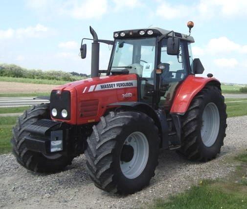
Massey Ferguson 7480, 7485 load sending hydraulic system - flowrate circuit
Massey Ferguson 7485, 7480 tractors are fitted with a closed centre hydraulic circuit with controlled pressure and flowrate.
Only tractors with a Powershift gearbox can be fitted, depending on
options, with a 150 l/min flowrate circuit.
It is composed of two separate high and low pressure circuits, supplied
by a variable displacement pump located on the external face of the
right-hand side cover.
This pump has a maximum output of 60 cm3 per revolution and is itself
fed by a 80 cm3 booster pump.
Both pumps are driven by a pinion fitted on the upper shaft of the PTO
located in the intermediate housing.
A “relay” pinion mounted on a bearing located on the internal side of
the cover, ensures the rotation of the driven pinion of the variable
displacement pump.

The MF 7480, 7485 booster pump fitted on the left-hand cover sucks oil
through a suction strainer to feed the common tank formed by the centre
housing, intermediate housing and gearbox.
The booster flowrate is then directed
towards the right-hand cover and passes through the main filter before
flowing towards the variable displacement pump and the oil manifold of
the centre housing to supply the following components:
- the trumpet housings
- the PTO clutch
- the hydraulic pump bearing
- the 4WD unit
- the handbrake mechanism
- the creeper unit (if fitted).
The variable displacement pump supplies one
or two priority blocks, depending on options, that are fitted on the
right-hand side cover:
- one block for MF 7485, 7480 tractors without hydraulic trailer braking
- two blocks for tractors with hydraulic trailer braking.
The first block supplies:
- its first priority, steering system
- its second priority, the 17 bar rear axle hydraulic circuit, the
auxiliary spool valves and the lift control valve.
- If a second block is fitted, it shares the first priority between the
steering circuit and the trailer braking.
Once the first priorities have been met, the remaining oil flow becomes
available to the auxiliary spool valves and the lift control valve.
All the pilot signals from the various high pressure valves are directed
to the priority block(s) to then be retransmitted to the variable
displacement pump controller.
The controller takes into account the pilot signal corresponding to the
function requiring the highest pressure.
Component characteristics
Suction strainer
- Type: cartridge
- Filtration threshold: 150
Booster pump
- Trademark Rexroth Sigma
- Capacity: 80 cm3 per revolution
- Output: 215 l/min at 2200 rpm
Main filter
- Filtration threshold: 15 u
- With differential pressure bypass: 3.5 bar
- With differential pressure switch: 2.4 bar
Safety valve
- Calibration: 22 bar
- fitted on the low pressure circuit
Safety valve
- Calibration: 5 bar
- No slave device used resupplies booster pump
- Switch: 5 bar (clogging indicator placed on main filter)
- Opens: 3 bar
- Closes: 2 bar
Massey Ferguson 7480, 7485 Variable displacement pump
- Trademark: Brueninghaus
- Type Axial pistons
- Variable capacity 0 to 60 cm3 per revolution
- Output: 0 to 150 l/min at 2200 rpm
- Min. pressure: 22 bar
- Max. pressure: 200 bar
- Internal lubrication with return to housing.
________________________________________________________________________________
 SPECS
 LOADERS
 MAINTENANCE
 PROBLEMS
________________________________________________________________________________________
 MF 1523
 MF 1531
 MF 135
 MF 1547
 MF 1635
________________________________________________________________________________________
 231
 231S
 235
 240
 241
________________________________________________________________________________________
_______________________________________________________________________________________
 255
 265
 274
 285
 375
________________________________________________________________________________________
________________________________________________________________________________________
 916X Loader
 921X Loader
 926X Loader
 931X Loader
 936X Loader
________________________________________________________________________________________
 941X Loader
 946X Loader
 951X Loader
 956X Loader
 988 Loader
________________________________________________________________________________________
 1655
 GS1705
 1742
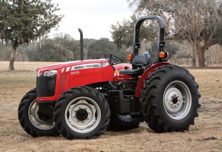 2635
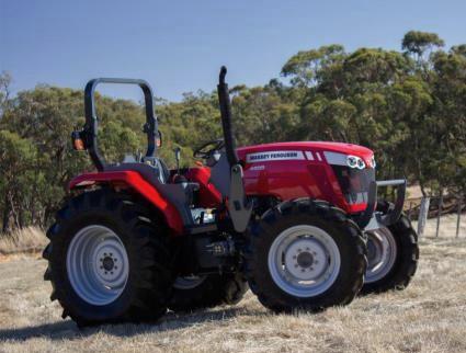 4608
________________________________________________________________________________________
 1080
 1100
 2615
 3050
 3060
________________________________________________________________________________________
 4708
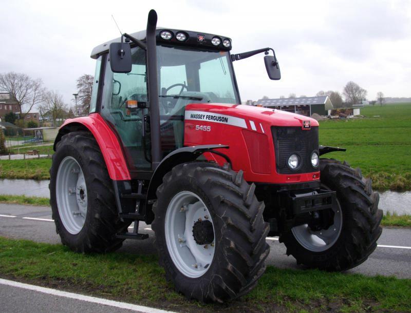 5455
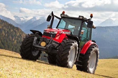 5450
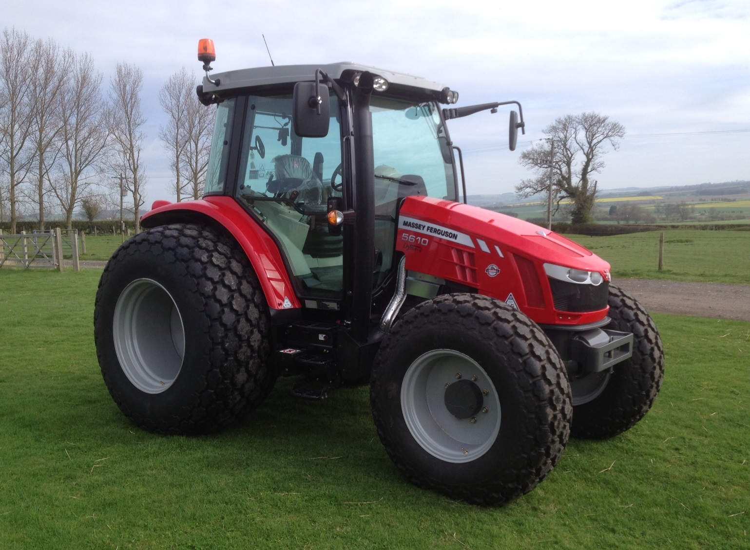 5610
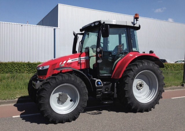 5613
________________________________________________________________________________________
 DL95 Loader
 DL100 Loader
 DL120 Loader
 DL125 Loader
 DL130 Loader
________________________________________________________________________________________
 DL135 Loader
 DL250 Loader
 DL260 Loader
 L90 Loader
 L100 Loader
________________________________________________________________________________________
 6499
 7480
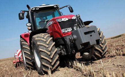 7618
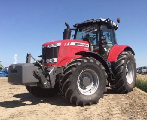 7726
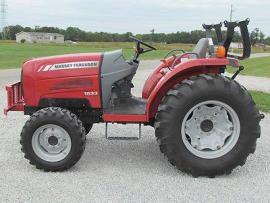 1533
________________________________________________________________________________________
 2604H
 2607H
 4455
 4610M
 4710
________________________________________________________________________________________
 L105E Loader
 L210 Loader
 1014 Loader
 1016 Loader
 1462 Loader
________________________________________________________________________________________
 1525 Loader
 1530 Loader
 232 Loader
 838 Loader
 848 Loader
________________________________________________________________________________________
 5712SL
 6713
 6715S
 7475
 7615
________________________________________________________________________________________
 7716
 7724
 8240
 8650
 8732
________________________________________________________________________________________
 246 Loader
 1036 Loader
 1038 Loader
 1080 Loader
 856 Loader