________________________________________________________________________________
Massey Ferguson 7495, 7499 hydraulic right-hand cover - Idler pinion and pump bearing block
Disassembling, reassembling and shimming of
the idler pinion
Disassembly
Remove the Massey Ferguson 7499, 7495 variable displacement pump.
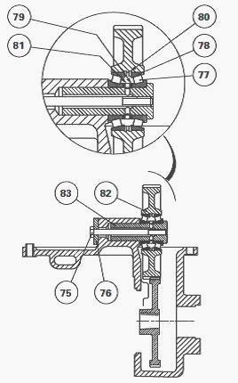
Unlock and remove bolts (75). Take out pin (83) and pinion (82) and pair
together the bearing cones and cups (77) (78) if they are to be reused.
Recover the shim(s)
(79) and spacer (81). On the pinion, remove the bearing cups (78) and
circlips (80).
Reassembly
Place the bearing cups (78) thrust against the previously fitted
circlips.
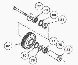
Reassemble the turning hub of the idler pinion (82) by assembling the
bearing cones (77), spacer (81), the shim(s) and pin (83).
If required, carry out the shimming of the idler pinion. Otherwise continue the reassembly operations. Assemble the pinion and pin on the cover.
Degrease the threads of bolt
(75) and lightly smear it with Loctite 241 or its equivalent. Fit washer
(76) and tighten the bolt
to a torque of 100 - 130 Nm. Manually check the rotation of the pinion.
Parts concerned by shimming
- The pinion (82), the circlips (80), the bearing cones and cups (77)
(78) and spacer (81).
- The clearance of the taper roller bearings is adjusted by shim(s) (79)
placed between the front cone (77) and spacer (81).
- To carry out the correct shimming of the bearings, place the cover in
a vice with the pump pinion (39) protruding as shown in Figure.
Shimming
Place the index of the dial gauge on the pinion (82). Push the pinion
strongly downwards, alternatively turning the pinion left and right in
order to correctly seat the
cone in the bearing cup.
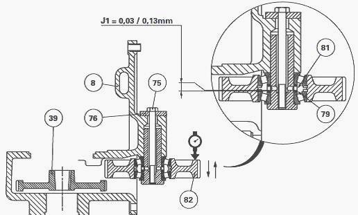
Reset the dial gauge to zero. Repeat the operation, this time pulling on
the pinion instead of pushing. Depending on clearance measured, select a
thickness of shim
(s) in order to provide a clearance of: J1 = 0.03 to 0.13 mm.
Wherever possible, shim the bearings to the minimum clearance. Fit the definitive shim(s) selected in operation. Degrease the threads of bolt (75) and lightly smear the threads with Loctite 241 or its equivalent.
Fit washer (76) and tighten
the bolt to a torque of 100 -
130 Nm. Manually check the rotation of the pinion.
Removing and refitting – Disassembling and reassembling the pump bearing
block
- Place the rear wheels in the wide track position.
- Uncouple the MF 7495, 7499 tractor between the gearbox and the
intermediate housing.
- Remove the creeper unit components (if fitted).
- Free the ratchet of the Park Lock (if fitted). Take out the toothed
sleeve after carefully noting its position.
Removal
Immobilise pinions (1) (82) using a bronze drift. Take out bolts and
extract pinion. Take out plug (8).
Using a threaded rod screwed into the
threaded hole in locating
pin (7), pull on it so as to free spacer (5).
Through the front opening of the intermediate housing, pull on the
bearing block to disengage it from the bore of the housing.
Refitting
Check that the hydraulic channels and ports of the spacer are not
obstructed.
Refit the bearing block.
Carry out operation in reverse order. Place the
groove of the spacer in the axis of the port provided for the plug (8).
Fit the locating pin, with
the flats lodged in the groove in the spacer. Tighten the plug.
Check that the bearing block assembly is correctly positioned and that it turns normally.
Fit pinion (1). Tighten bolts (4) previously smeared
with Loctite 241 or its
equivalent to a torque of 72 - 96 Nm.
Disassembly
Remove the bearing block.
Take off circlip (10).
Extract bearings (6)
and recover spacer (5).
Reassembly
Clean and check the components. Replace any parts found to be defective.
Using a press and an appropriate fixture insert bearings (6), placing
spacer (5) between them.
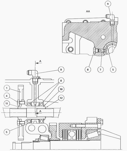
Fit circlip (10). Check for the presence of circlip (12) on the upper
shaft of the power take off. Refit the bearing block and fit the pinion.
- The union (9) has a calibrated port for the lubrication of bearings
(6).
- If fitted, unclamp the ratchet and position the sleeve of the Park
Lock.
- The long part of the ratchet must face the drive pinion.
- Refit and adjust the creeper unit components (if fitted).
- Couple the MF 7495, 7499 tractor between the gearbox and the
intermediate housing.
- Replace the wheels in their initial positions. Tighten the wheel nuts
or studs.
- Check the operation of all the controls.
- Carry out a road test.
- Check the oil tightness of the mating faces and hydraulic unions.
________________________________________________________________________________
 SPECS
 LOADERS
 MAINTENANCE
 PROBLEMS
________________________________________________________________________________________
 MF 1523
 MF 1531
 MF 135
 MF 1547
 MF 1635
________________________________________________________________________________________
 231
 231S
 235
 240
 241
________________________________________________________________________________________
_______________________________________________________________________________________
 255
 265
 274
 285
 375
________________________________________________________________________________________
________________________________________________________________________________________
 916X Loader
 921X Loader
 926X Loader
 931X Loader
 936X Loader
________________________________________________________________________________________
 941X Loader
 946X Loader
 951X Loader
 956X Loader
 988 Loader
________________________________________________________________________________________
 1655
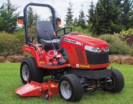 GS1705
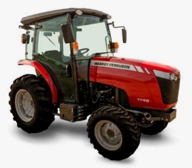 1742
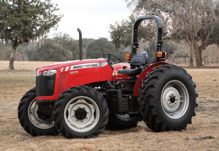 2635
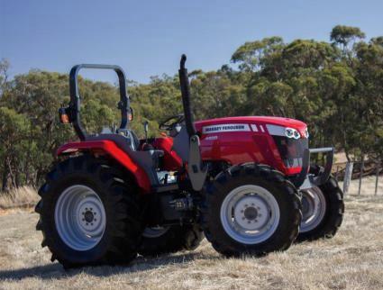 4608
________________________________________________________________________________________
 1080
 1100
 2615
 3050
 3060
________________________________________________________________________________________
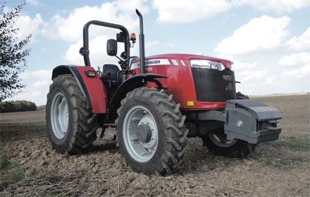 4708
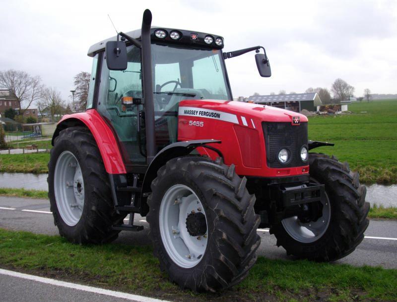 5455
 5450
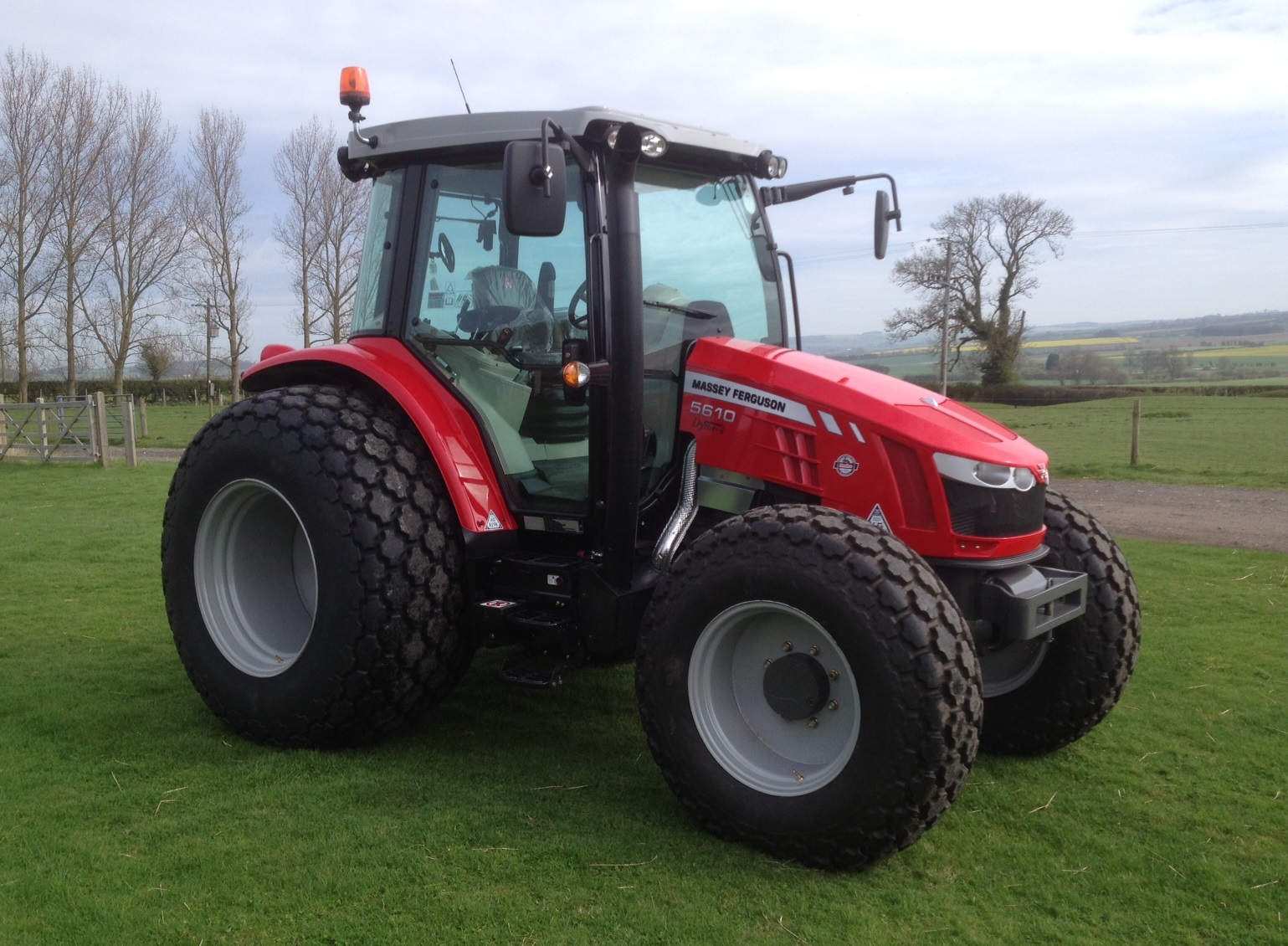 5610
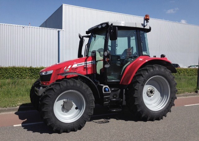 5613
________________________________________________________________________________________
 DL95 Loader
 DL100 Loader
 DL120 Loader
 DL125 Loader
 DL130 Loader
________________________________________________________________________________________
 DL135 Loader
 DL250 Loader
 DL260 Loader
 L90 Loader
 L100 Loader
________________________________________________________________________________________
 6499
 7480
 7618
 7726
 1533
________________________________________________________________________________________
 2604H
 2607H
 4455
 4610M
 4710
________________________________________________________________________________________
 L105E Loader
 L210 Loader
 1014 Loader
 1016 Loader
 1462 Loader
________________________________________________________________________________________
 1525 Loader
 1530 Loader
 232 Loader
 838 Loader
 848 Loader
________________________________________________________________________________________
 5712SL
 6713
 6715S
 7475
 7615
________________________________________________________________________________________
 7716
 7724
 8240
 8650
 8732
________________________________________________________________________________________
 246 Loader
 1036 Loader
 1038 Loader
 1080 Loader
 856 Loader