________________________________________________________________________________
Massey Ferguson 7614, 7616 tractor gearbox - Kinematics and Synchronizers
Kinematics of the Massey Ferguson 7614, 7616
GBA25 gearbox
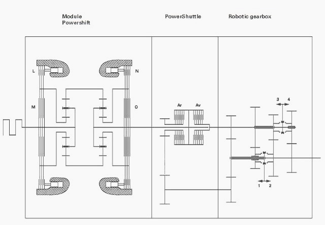
(Av) Forward clutch (Ar) Reverse clutch (L) Planetary gear brake, Power
shift module front epicyclic gear train (M) Planetary gear clutch, Power
shift module front
epicyclic gear train (N) Planetary gear brake, Power shift module rear
epicyclic gear train (O) Planetary gear clutch, Power shift module rear
epicyclic gear train
MF 7614, 7616 Power shift module kinematics
Ratio A (1/1.5)
The front epicyclic gear train piston (69) is not pressurised; the
clutch (M) is tightened by the Belleville washers.
The sun gear and the planet-carrier are attached, thereby creating a mechanical lock; the front epicyclic gear train is thus "locked" and its ratio is 1/1. The rear epicyclic gear train piston (104) is pressurised.
The
brake (N) is tightened and holds the sun gear in relation to the
housing. The rear epicyclic gear train turns and reduces the input
speed.
Ratio B (1/1.22)
The front epicyclic gear train piston (69) is pressurised; the clutch
(M) is loosened.
The brake (L) is tightened and holds the sun gear (72)
in relation to the housing.
The front epicyclic gear train turns and multiplies the input speed.
The
rear epicyclic gear train is in the same position as at ratio A.
Ratio C (1/1)
The two epicyclic gear train pistons (69)(104) are not pressurised. The
two clutches (M) and (O) are tightened by their respective Belleville
washers.
The sun gear is attached to the planet-carrier in each epicyclic gear train, thereby creating a mechanical lock.
The two epicyclic gear trains are "locked",
the module input speed is
the same at its output and the ratio is 1/1.
Ratio D (1/0.813)
The front epicyclic gear train piston (69) is pressurised; the clutch
(M) is loosened.
The brake (L) is tightened and holds the sun gear (72)
in relation to the housing.
The front epicyclic gear train turns and multiplies the input speed.
The
second epicyclic gear train is "locked" as at ratio C; its ratio is 1/1.
Kinematics of the Power Shuttle
When the Massey Ferguson 7616, 7614 tractor transmission is in neutral,
the Power Shuttle clutches are not pressurised.
In forward position, the "Av" clutch is engaged, and directly transmits drive from the Power shift to the primary shaft of the gearbox.
In reverse position, the "Ar" clutch is
engaged, and transmits drive to
a mainshaft then to a 2nd ratio pinion on the secondary shaft of the
main gearbox.
Kinematics of the main gearbox
Range 1 - The reduction is carried out on three gear trains. The first
gear train drives the second train via the 1st gear synchronisers, then
the third train.
Range 2 - The reduction is carried out on the first gear train. The 2nd
gear synchronisers secure the 2nd ratio pinion to the secondary shaft.
Range 3 - The reduction is carried out on the third gear train. The
primary shaft is secured to the 3rd ratio pinion by the 3rd gear
synchronisers.
Range 4 - The reduction is carried out on the fourth gear train. The
primary shaft is secured to the 4th ratio pinion by the 4th gear
synchronisers.
Synchronisers of the MF 7616, 7614 gearbox
Single and double cone synchronisers
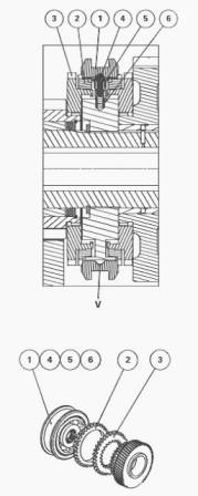
Single (Ranges 3 and 4) cone synchronisers -
(1) Sliding coupler (2) Cone (brake) (3) Coupling flange (4) Ball
bearing (5) Pressure connectors (6) Spring
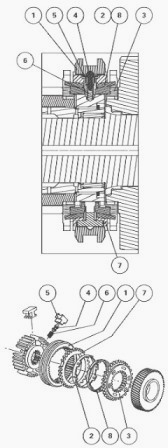
Double (Ranges 1 and 2) cone synchronisers - (1) Sliding coupler (2)
Cone (brake) (3) Coupling flange (4) Ball bearing (5) Pressure
connectors (6) Spring (7) Ring (8) Cone (brake)
Locked position
When the sliding coupler (1) moves towards the gear to be locked, it
presses against the cone (2) which in turn presses against the male cone
of the coupling flange
(3) via ball bearings (4) and pressure elements (5).
When the
synchronisation is set, the sliding coupler (1) can mesh and silently
lock with the teeth of the coupling
flange (3).
Neutral position
Sliding coupler (1) is in the middle position.
The balls (4) are pushed
into the V groove of the sliding coupler by pressure springs (6). In
this neutral position, the
sliding coupler is locked by three balls held in place by the pressure
springs.
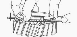
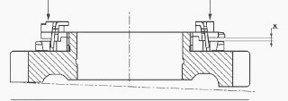
Check
If the single cone synchronisers (11), (23) and (31) have been
disassembled, check the wear to the cone (2) as follows:
Stack the coupling flange (3) and cone (2) on the relevant pinion.
Correctly position the cone (2) on the male cone of the coupling flange,
revolving several times and applying manual pressure.
Using a set of thickness shims, measure dimension X at three equidistant
points.
Calculate the average of the three values and proceed as described
below, depending on the result obtained. On a new synchroniser,
dimension X must be 1.5 mm
maximum.
After operation, if X is less than or equal to 0.80 mm:
- replace the cone (2);
- check the measurement of X again, using the same process. If dimension
X remains incorrect, also replace the coupling flange (3) or, if
necessary, the complete
synchroniser.
Advantages and operation
The double cone synchroniser has the following advantages: improved
reliability and increased resistance to MF 7614, 7616 transmission
loads.
The operating
principle of the double cone synchronizer is similar to that of the
single cone synchroniser. The positions (locked and neutral) are
obtained in the same way.
Check
When disassembling the double cone synchroniser of the mechanical
reverse shuttle, check the cones (2) and (8) for wear as follows:
Stack the coupling flange (3), cones (2) and (8) and ring (7).
Correctly position the ring (7) on the cones (2) and (8), revolving them
alternately each several turns and applying pressure manually.
Using a set of thickness shims, measure dimension X at three equidistant
points. Calculate the average of the three values and proceed as
described below,
depending on the result obtained. On a new synchroniser, dimension X
must be 1.6 mm minimum.
After operation, if X is less than or equal to 0.60–0.80 mm:
- replace the cones (2) and (8);
- check the measurement of X again, using the same process. If dimension
X remains incorrect, also replace the ring (7) or, if necessary, the
complete
synchroniser.
Main gearbox robotic control
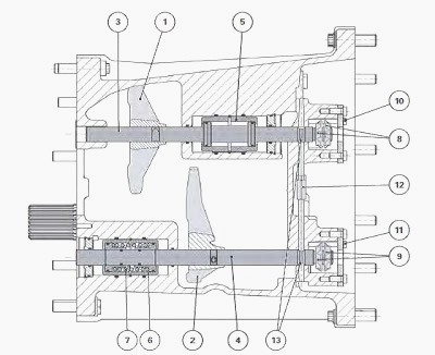
The synchronisers are controlled conventionally by forks (1) and (2) and
selector rails (3) and (4). The selector rails are controlled
hydraulically. The selector rails
are fitted on double-acting pistons (5) and (6).
On the selector rail (4) that controls the 1st and 2nd gear synchroniser, the piston (6) is damped by a spring (7) to smoothen shifting between ranges 1 and 2. The selector rails are adjusted by tightening or loosening the adjustable stops (8) and (9).
Once adjusted, the stops are held in rotation by screws (10) and (11). A safety pin (12) prevents the selector rails from being engaged simultaneously. When a selector rail is engaged, the pin locks the other one at the groove (13).
________________________________________________________________________________
 SPECS
SPECS LOADERS
 MAINTENANCE
 PROBLEMS
________________________________________________________________________________________
 MF 1523
 MF 1531
 MF 135
 MF 1547
 MF 1635
________________________________________________________________________________________
 231
231 231S
231S 235
235 240
240 241
241________________________________________________________________________________________
 255
255 265
265 274
274 285
285 375
375________________________________________________________________________________________
________________________________________________________________________________________
 916X Loader
 921X Loader
 926X Loader
 931X Loader
 936X Loader
________________________________________________________________________________________
 941X Loader
 946X Loader
 951X Loader
 956X Loader
 988 Loader
________________________________________________________________________________________
 1655
1655 GS1705
 1742
1742 2635
2635 4608
4608________________________________________________________________________________________
 1080
1080 1100
1100 2615
2615 3050
3050 3060
3060________________________________________________________________________________________
 4708
4708 5455
5455 5450
5450 5610
5610 5613
5613________________________________________________________________________________________
 DL95 Loader
 DL100 Loader
 DL120 Loader
 DL125 Loader
 DL130 Loader
________________________________________________________________________________________
 DL135 Loader
 DL250 Loader
 DL260 Loader
 L90 Loader
 L100 Loader
________________________________________________________________________________________
 6499
6499 7480
7480 7618
7618 7726
7726 1533
1533________________________________________________________________________________________
 2604H
2604H 2607H
2607H 4455
4455 4610M
4610M 4710
4710________________________________________________________________________________________
 L105E Loader
 L210 Loader
 1014 Loader
 1016 Loader
 1462 Loader
________________________________________________________________________________________
 1525 Loader
 1530 Loader
 232 Loader
 838 Loader
 848 Loader
________________________________________________________________________________________
 5712SL
 6713
6713 6715S
6715S 7475
7475 7615
7615________________________________________________________________________________________
 7716
7716 7724
7724 8240
8240 8650
8650 8732
8732________________________________________________________________________________________
 246 Loader
 1036 Loader
 1038 Loader
 1080 Loader
 856 Loader