
________________________________________________________________________________
Massey Ferguson 7618, 7620 hydraulic system - Electrohydraulic auxiliary spool valves
The Bosch/Rexroth SB23 LS spool valves controlling supply to the
hydraulic couplers are comprised of: an hydraulic part; an electric
hydraulic part.
Electric hydraulic part comprising:
- an ON/OFF solenoid valve and a 3-way pressure relief valve located on
the end plate of the distribution block,
- a pilot valve fitted in the electric hydraulic unit.
MF 7618, 7620 electrohydraulic control spool valves are supplied by high
flow rate, high pressure oil from the priority blocks.
When no functions are being activated, the entire flow rate is directed towards the spool valves. When certain functions are being supplied, the excess flow then remains available to the auxiliary spool valves.
The adjustment of the flow rate, expressed as a percentage, may be displayed on the onboard computer (Datatronic) by the operator.
Joystick-controlled electrohydraulic spool valves are fitted with a floating Kick-out position (automatic return to neutral). The main spool of the spool valve directs oil towards the outlet ports A or B.
Each outlet port is linked to the LS pilot line of the variable displacement pump regulating valve via the priority block(s).
The spool valves consist of
both electronic and hydraulic components, the latter containing spools
and valves. Some elements cannot be repaired as spare parts.
Different types of spool valve block components
A spool valve block can consist of three, four or five of the following
components. It can combine components of similar type of or different
types.
Component a
Electrohydraulic unit (Joystick)
Component b
Electrohydraulic component (Dual Control)
Component c
Mechanically controlled component.
Couplers
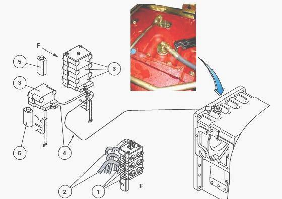
The quick-disconnect couplings are held by a bracket on the centre
housing. They are sealed by covers of different colours (red, green,
black or yellow)
corresponding respectively to hydraulic ports A and B of auxiliary spool
valves.
When the Massey Ferguson 7618, 7620 auxiliary spool valve is at rest, a lever system (1) allows existing pressure to be relieved into the hydraulic hoses (2).
These hoses link the spool valves with the concerned couplers (3). By acting on this system, the clean oil under pressure is directed to the return via a hose and pipe assembly (4) connected to the upper part of the intermediate housing.
This drop in
pressure facilitates the connecting of the male coupler to the female
coupler. The contaminated oil, coming from the separation of the
couplers, flows into flexible
and transparent tanks (5) located on either side of the third-point
linkage.
Pressure relief valve and electrohydraulic unit operation
When the ON/OFF solenoid valve located on end plate is open, the flow
from the pump is directed to the 3-way pressure relief valve.
The 3-way pressure relief valve supplies the pilot valve with a pressure
of 21 - 24 bar via a pressure balancing valve.
The pilot valve receives a signal from the digital device and moves the
main spool of Massey Ferguson 7618, 7620 auxiliary electric hydraulic
spool valve according
to the information received from the Joystick.
The digital device is informed of the position of the main spool by a
displacement sensor.
The pilot valve and the digital device are housed in the unit fixed
below the spool valve.
The pilot valve is protected from possible oil contamination by a set of
FP filters (25 microns).
Electronic unit channels P and R are connected to channels P1 and R1 of
the auxiliary electrohydraulic spool valve.
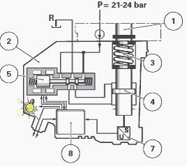
(1) Main electric hydraulic valve spool (2) Electrohydraulic unit (3)
Return spring (4) Piston (5) Pilot valve (6) Digital electronic system
(7) Displacement sensor, FP
- Set of filters (25 microns), P - Pressure, R - Return
Operation of MF 7618, 7620 auxiliary electrohydraulic spool valve
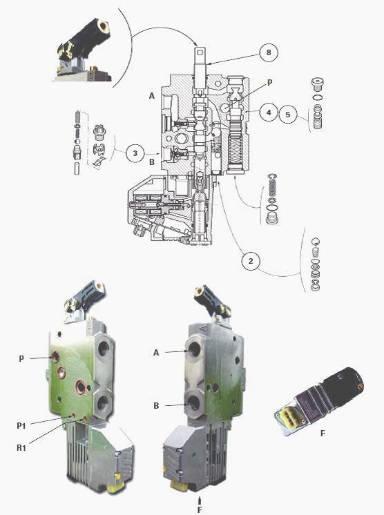
When spool (1) is moved electro-hydraulically upwards by the pilot valve
(5), oil penetrates via channel P and travels to the flow regulation
control spool restrictor (5)
and the grooves of the main spool (1).
The oil is then carried towards a main channel and lifts the ball of valve to enter a chamber. Displacement of the spool (1) simultaneously opens the one-way valve (3).
The oil flows from the chamber towards port B and returns to the housing through port A via the hydraulic slave device. The operating principle is identical when the spool (1) is electro-hydraulically moved down by the pilot valve (5).
The oil flows from the chamber towards port A and returns to the housing through port B via the hydraulic slave device. The electrohydraulic spool valves can be manually controlled using a lever screwed onto the reversing lever.
________________________________________________________________________________
________________________________________________________________________________________
 SPECS
SPECS LOADERS
 MAINTENANCE
 PROBLEMS
________________________________________________________________________________________
 MF 1523
 MF 1531
 MF 135
 MF 1547
 MF 1635
________________________________________________________________________________________
________________________________________________________________________________________
 231
231 231S
231S 235
235 240
240 241
241________________________________________________________________________________________
 255
255 265
265 274
274 285
285 375
375________________________________________________________________________________________
________________________________________________________________________________________
 916X Loader
 921X Loader
 926X Loader
 931X Loader
 936X Loader
________________________________________________________________________________________
 941X Loader
 946X Loader
 951X Loader
 956X Loader
 988 Loader
________________________________________________________________________________________
 1655
1655 GS1705
 1742
1742 2635
2635 4608
4608________________________________________________________________________________________
 1080
1080 1100
1100 2615
2615 3050
3050 3060
3060________________________________________________________________________________________
 4708
4708 5455
5455 5450
5450 5610
5610 5613
5613________________________________________________________________________________________
 DL95 Loader
 DL100 Loader
 DL120 Loader
 DL125 Loader
 DL130 Loader
________________________________________________________________________________________
 DL135 Loader
 DL250 Loader
 DL260 Loader
 L90 Loader
 L100 Loader
________________________________________________________________________________________
 6499
6499 7480
7480 7618
7618 7726
7726 1533
1533________________________________________________________________________________________
 2604H
2604H 2607H
2607H 4455
4455 4610M
4610M 4710
4710________________________________________________________________________________________
 L105E Loader
 L210 Loader
 1014 Loader
 1016 Loader
 1462 Loader
________________________________________________________________________________________
 1525 Loader
 1530 Loader
 232 Loader
 838 Loader
 848 Loader
________________________________________________________________________________________
 5712SL
 6713
6713 6715S
6715S 7475
7475 7615
7615________________________________________________________________________________________
 7716
7716 7724
7724 8240
8240 8650
8650 8732
8732________________________________________________________________________________________
 246 Loader
 1036 Loader
 1038 Loader
 1080 Loader
 856 Loader