________________________________________________________________________________
Massey Ferguson 7614, 7615 robotic mechanical gearbox - Primary and secondary shafts
Drain the transmission oil. Split the MF 7614, 7615 tractor in order to
remove only the robotic gearbox (if servicing only concerns the robotic
gearbox) or the complete Dyna-4 unit (then split the two housings).
Remove:
- all hydraulic pipes fitted to the unit housing
- the PTO shaft.
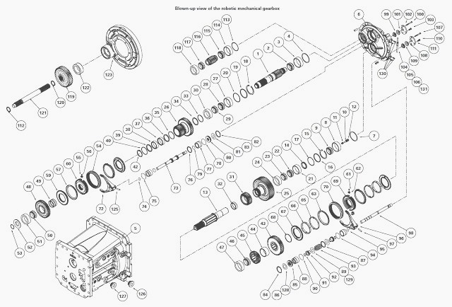
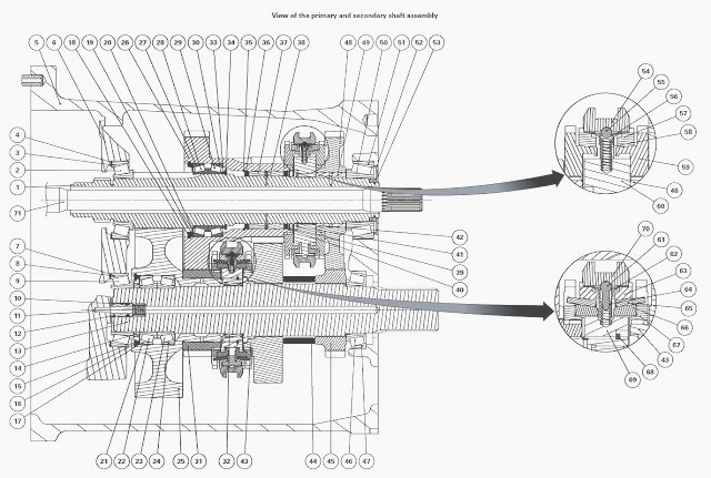
Removing the primary and secondary shafts
Rig up four makeshift legs on which to set the unit vertically.
Use an
M14 screw or threaded rod, and weld on a nut to ensure a minimum
distance of 120 mm
between the unit and the work surface.
Position the unit on the legs, with the cover (6) on top.
Take off the covers (102) and (111). Unscrew the castellated nuts
(99)(101) and (108)(109). Retighten the safety finger rod (106) to its
maximum.
Remove the two plugs (126) and (127). Drive out the two pins (97) and (125) holding the forks on the selector rails. The pins will fall into the gearbox housing.
They
must be recovered when the Massey Ferguson 7614, 7615 gearbox is
disassembled.
Remove the circlip at the rear of the gearbox (84).
Using a plastic hammer, remove the selector rail (98) towards the rear of the gearbox. The rail control piston assembly is fitted to the rail and is removed with it.
Part
of the sleeve remains in the cylinder. If it must be removed, take off
the circlip (87) and extract the sleeve. Remove the screws (A) from the
cover (6).
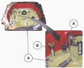
Install two screws (B) in the threaded holes in order to lift up the
cover (6).
Remove the cover (6). Recover the bearing cups (3), (8) and (114) and
the shims (4), (7) and (113).
Recover the lubricating pipe (12), the seal (10) and the spring (11). Remove the circlip (82). Using a plastic hammer, remove the selector rail (73) towards the front of the gearbox.
The rail control piston assembly is fitted to the rail
and is removed with it.
Part of the sleeve remains in the cylinder. If it must be removed, take
off the circlip (76) and extract the sleeve.
Disassembling and reassembling the selector rail (ranges 1 and 2)
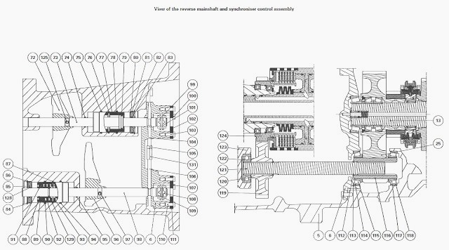
Clamp the rail (98) in a vice equipped with protective jaws.
Tighten the two pistons (92) in the vice to compress the spring.
Remove a snap ring (91). Remove the pistons (92) and the spring (93).
Replace the seals (129) on the rail (98).
Carry out operations in reverse order to assemble the selector rail.
Turn the forks (72) and (96) inwards in the MF 7615, 7614 tractor
gearbox to allow them to enter the housing.
Place service tool in the primary and secondary shafts.
Sling the tool using a pulley hoist or a suitable lifting system. Extract the two shafts (1) and (13) from the gearbox housing. Take care when the 1st/2nd gear synchronizer is passing beside the reverse shaft support.
The total
weight of the two shafts is approximately 44 kg (lower shaft line = 27
kg, upper shaft line = 17
kg).
Remove the assembly and place it on a workbench.
Remove the service tool
and split the two shafts. If required, extract the bearing cups (47),
(51) and (118) from
the gearbox housing. If necessary, remove deflector (52).
Reinstall the primary and secondary shafts
Ensure all parts are clean and in good condition. Check that the
lubricating ports and range control ports are clean.
Replace all the "O" rings, greasing them lightly before assembly.
Do not
forget to replace the "O" rings (74), (75), (78), (90), (94) and (95) in
the selector rail bores
inside the housing. Check the presence of the bearing cups (47), (51)
and (118) in the housing (5).
Assemble the shafts (1) and (13).
Install the forks (72) and (96) on the synchronizer sliders. The offset
side of the fork must be turned towards the front of the Massey Ferguson
7615, 7614 tractor.
The two forks are identical. They have the same reference. Install the two shafts in the housing. At the same time, Install the reverse transfer pinion (116) fitted with the two bearing cones (115) and (117).
Ensure the pinion
(116) is positioned correctly. The marks on the teeth should be turned
towards the bottom of the housing.
Reinstall the lubricating pipe (12) fitted with a new "O" ring (10) and
the spring (11).
If the sleeve (77) and the circlip (76) have been removed, grease the sleeve, insert it into the cylinder, then fit the circlip (77). Thread the selector rail (73) with the lightly greased piston assembly into its housing.
To help insert the selector rail into the fork, use a
pin punch to hold the fork in
place. Install the plug (80) fitted with two new "O" rings (81) (83).
Install the circlip (82).
If the sleeve (88) and circlip (87) have been removed, grease the sleeve, insert it into the cylinder, then fit the circlip (87). Thread the selector rail (98) with the lightly greased piston assembly into its housing.
To help insert the selector rail into the fork, use a pin punch to hold the fork in place. Mount the plug (85) fitted with two new "O" rings (86) (128). Install the circlip (84).
Align the holes in the forks (72) and (96)
with those in the corresponding
selector rails.
Insert new pins to attach the forks to the selector rails. Install the
plugs (126) and (127).
Check the interlock mechanism is in position and retighten the rods
(104) and (106) to their maximum tightness.
Install the four switch thrust pins (130) using a bit of grease to hold
them in position. In the cover (6), Install the bearing cones (3), (8)
and (114) smeared with grease
to hold them in position.
Also Install:
- the original thickness of shims if the roller bearings have not been
replaced
- the calculated thickness of shims if the roller bearings have been
replaced.
Put the cover back on (6). Install the cover (6) screws smeared with
Loctite 242. Tighten to a torque of 57–77 Nm.
Reinstall the ring (52) with the lubricating port turned towards the top
of the gearbox. Fix it in position with four punchmarks.
Adjust the selector rails and forks. Adjust the interlock mechanism.
________________________________________________________________________________
 SPECS
SPECS LOADERS
 MAINTENANCE
 PROBLEMS
________________________________________________________________________________________
 MF 1523
 MF 1531
 MF 135
 MF 1547
 MF 1635
________________________________________________________________________________________
 231
231 231S
231S 235
235 240
240 241
241________________________________________________________________________________________
 255
255 265
265 274
274 285
285 375
375________________________________________________________________________________________
________________________________________________________________________________________
 916X Loader
 921X Loader
 926X Loader
 931X Loader
 936X Loader
________________________________________________________________________________________
 941X Loader
 946X Loader
 951X Loader
 956X Loader
 988 Loader
________________________________________________________________________________________
 1655
1655 GS1705
 1742
1742 2635
2635 4608
4608________________________________________________________________________________________
 1080
1080 1100
1100 2615
2615 3050
3050 3060
3060________________________________________________________________________________________
 4708
4708 5455
5455 5450
5450 5610
5610 5613
5613________________________________________________________________________________________
 DL95 Loader
 DL100 Loader
 DL120 Loader
 DL125 Loader
 DL130 Loader
________________________________________________________________________________________
 DL135 Loader
 DL250 Loader
 DL260 Loader
 L90 Loader
 L100 Loader
________________________________________________________________________________________
 6499
6499 7480
7480 7618
7618 7726
7726 1533
1533________________________________________________________________________________________
 2604H
2604H 2607H
2607H 4455
4455 4610M
4610M 4710
4710________________________________________________________________________________________
 L105E Loader
 L210 Loader
 1014 Loader
 1016 Loader
 1462 Loader
________________________________________________________________________________________
 1525 Loader
 1530 Loader
 232 Loader
 838 Loader
 848 Loader
________________________________________________________________________________________
 5712SL
 6713
6713 6715S
6715S 7475
7475 7615
7615________________________________________________________________________________________
 7716
7716 7724
7724 8240
8240 8650
8650 8732
8732________________________________________________________________________________________
 246 Loader
 1036 Loader
 1038 Loader
 1080 Loader
 856 Loader