________________________________________________________________________________
Massey Ferguson 7716, 7718 hydraulic system – Load Sending Left-hand cover plate
With the exception of the profile of certain hydraulic components, the
design and operation of the left-hand cover plate are virtually
identical for tractors equipped with 110 l/min Load Sensing hydraulic
equipment (GPA20, GPA30 or GPA40 rear axles) or 150 l/min Load Sensing
(LS) hydraulic equipment (GPA40).
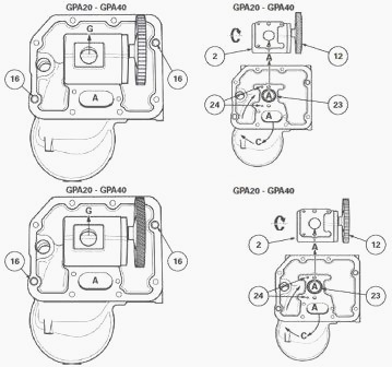
MF 7716, 7718 tractors equipped with a GPA20
or GPA40 rear axle
The left-hand cover plate is Installed on the centre housing.
It supports (on the internal face):
- the charge pump (2) with a capacity of 60 cm3/revolution, 71
cm3/revolution or 80 cm3/revolution (according to specification) (GPA20
and GPA40 rear axles) (110 l/min LS hydraulic system) or the charge pump
(2) with a capacity of 100 cm3/revolution (GPA40 rear axles) (150 l/min
LS hydraulic system)
- the drive gear (12) fitted on the charge pump
- the suction manifold (4);
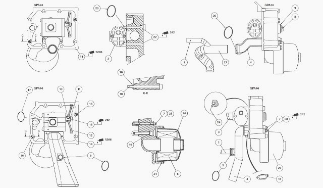
(1) Continuity pipe (2) Charge pump (3) Charge pipe (4) Suction manifold
(suction and resupply) (5) "O" ring (6) 150 suction strainer (7) Studs
(8) Plug (9) Seal (10) Screw (11) Washer (12) Gear (13) Key (14)
Left-hand cover plate (15) Nut (16) Locating pins (17) "O" ring (18)
Flat seal (19) Screw
(20) Strainer bowl (21) "O" ring (22) Screw (23) "O" ring (24) Dowels
(26) "O" ring (27) Suction pipe (28) Nuts
on the external face:
- the 150 micron suction strainer (6).
Massey Ferguson 7716, 7718 engine movement transmitted to the gear (1)
via the shaft (5) drives the gear (12) for the charge pump (2).
The oil is sucked in by the manifold (4). It is then directed to the
strainer and the charge pump (2) via a channel moulded into the cover
plate.
The oil delivered by the charge pump (2) is directed to the variable displacement pump (41) via the charge pipe (3).
When the high
pressure hydraulic slave devices (e.g. auxiliary spool valves) are not
activated, the charge pump (2) is resupplied via the 5 bar safety valve
(44).
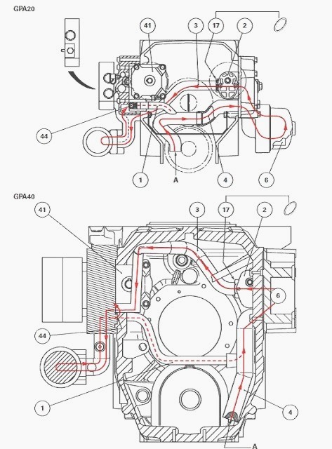
(1) Continuity pipe (2) Charge pump (3) Charge pipe (4) Suction manifold
(suction and resupply) (41) Variable displacement pump (44) 5 bar safety
valve
MF 7716, 7718 tractors equipped with a GPA30 rear axle
The left-hand cover plate (14) is Installed on the intermediate housing.
It supports on the internal face:
- the charge pump (2) with a capacity of 60 cm3/revolution (GPA30 rear
axle)
- the drive gear (12) fitted on the charge pump
- the suction manifold (4);
on the external face:
- the 150 micron suction strainer (6).
The engine movement transmitted to the gear (1) via the shaft (5) drives
the gear (12) for the charge pump (2). The oil is sucked in by the
manifold (4).
It is then directed to the strainer (6) and the charge pump (2) via a channel moulded into the cover plate.
The oil delivered by the charge pump (2) is directed to the variable displacement pump (41) via the charge pipes (3) and (54).
When the high pressure hydraulic
slave devices (e.g. auxiliary spool valves) are not activated, the
charge pump (2) is re-supplied via the 5 bar safety valve (44), the pipe
(55) and the manifold (4).
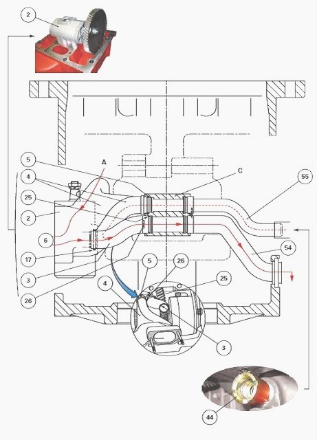
(2) Charge pump (3) Charge pipe (4) Suction manifold (suction and
resupply) (5) "O" ring (6) 150 suction strainer (17) "O" ring (25) "O"
ring (26) Mecanindus pin (44) Safety valve (54) Charge pipe
(55) Continuity pipe from 5 bar safety valve, C - Partition integral to
the intermediate housing
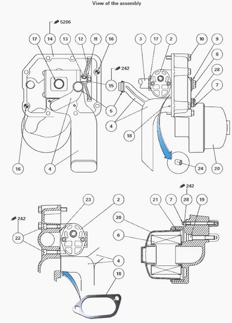
(2) Charge pump (3) Charge pipe (4) Suction manifold (suction and
resupply) (5) "O" ring (6) 150 suction strainer (7) Studs (8) Plug (9)
Seal (10) Screw (11) Washer (12) Gear (13) Key (14) Left-hand cover
plate (15) Nut (16) Locating pins (17) "O" ring (18) Flat seal (19)
Screw (20) 150 strainer bowl (21) "O" ring (22) Screw (23) "O" ring
(24) Dowels (28) Nuts
Identification of channels and ports
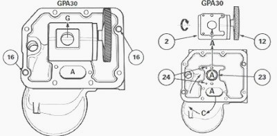
on the cover plate
A - Suction port (oil from manifold (4) and continuity pipe (1) or (55)
(depending on assembly)) C - 150 suction strainer G - Charge port (oil
directed to variable displacement pump via the charge pipe (3) or the
charge pipes (3) and (54) depending on assembly).
________________________________________________________________________________
 SPECS
SPECS LOADERS
 MAINTENANCE
 PROBLEMS
________________________________________________________________________________________
 MF 1523
 MF 1531
 MF 135
 MF 1547
 MF 1635
________________________________________________________________________________________
 231
231 231S
231S 235
235 240
240 241
241________________________________________________________________________________________
 255
255 265
265 274
274 285
285 375
375________________________________________________________________________________________
________________________________________________________________________________________
 916X Loader
 921X Loader
 926X Loader
 931X Loader
 936X Loader
________________________________________________________________________________________
 941X Loader
 946X Loader
 951X Loader
 956X Loader
 988 Loader
________________________________________________________________________________________
 1655
1655 GS1705
 1742
1742 2635
2635 4608
4608________________________________________________________________________________________
 1080
1080 1100
1100 2615
2615 3050
3050 3060
3060________________________________________________________________________________________
 4708
4708 5455
5455 5450
5450 5610
5610 5613
5613________________________________________________________________________________________
 DL95 Loader
 DL100 Loader
 DL120 Loader
 DL125 Loader
 DL130 Loader
________________________________________________________________________________________
 DL135 Loader
 DL250 Loader
 DL260 Loader
 L90 Loader
 L100 Loader
________________________________________________________________________________________
 6499
6499 7480
7480 7618
7618 7726
7726 1533
1533________________________________________________________________________________________
 2604H
2604H 2607H
2607H 4455
4455 4610M
4610M 4710
4710________________________________________________________________________________________
 L105E Loader
 L210 Loader
 1014 Loader
 1016 Loader
 1462 Loader
________________________________________________________________________________________
 1525 Loader
 1530 Loader
 232 Loader
 838 Loader
 848 Loader
________________________________________________________________________________________
 5712SL
 6713
6713 6715S
6715S 7475
7475 7615
7615________________________________________________________________________________________
 7716
7716 7724
7724 8240
8240 8650
8650 8732
8732________________________________________________________________________________________
 246 Loader
 1036 Loader
 1038 Loader
 1080 Loader
 856 Loader