________________________________________________________________________________
Massey Ferguson 8280 gearbox - Input unit with power shuttle
The power unit with power shuttle is in the form of an interchangeable module on which a reverse shuttle is assembled that can power the forward or reverse gear.
It is made of two distinct parts: the power shuttle and the Dynashift.
Dynashift
The MF 8280 gearbox dynashift electro-hydraulically controls four
powershift ratios using a lever mounted to the left under the steering
wheel. It is located between
the power shuttle and the driving gear mounted in the rear housing.
The Dynashift function is performed by two epicyclic gear trains
associated with two hydraulic clutches. For information on operation.

A removable flange (2) supports the front end of the selector rails
(Fig.21).
This assembly enables easy horizontal removal of the input unit
(Fig.22).

Uncouple the Massey Ferguson 8280 tractor between the engine and the
gearbox.
Drain the gearbox.
Remove the selector cover and through the opening, over the gearbox,
remove the screw (1) attaching the flange (2) (Fig.21).
Move the flange away from the housing by making it slide along the
selector rails.
The flange (2) is positioned on the rear housing of the input unit by
means of two cotter pins (3) (Fig.23).

Remove the clutch cover plate.
Remove the power shuttle control unit.
Remove and mark the position of the hydraulic pipes connected to the
following functions:
- gearbox lubrication
- Dynashift low pressure
- power shuttle rear clutch low pressure
Remove the power shuttle front clutch.
Take out the PTO shaft (1) from the MF 8280 gearbox (Fig.22) and mark
its position.
Disconnect and remove the progressive sensor located above the gearbox.
Sling the input unit using tool , a locally made handling bar and a
lifting device adapted as per Fig.22.
Before using the sling, remove the four screws (64) (L = 145 mm) unless
removed beforehand they will not be accessible to the "U" profile of the
tool.

Remove the remaining screws (64A) (L = 145 mm) securing the input unit
to the gearbox (Fig.24).
Do not intervene on the short screws (70) (L = 25 mm) so as to avoid
splitting the unit.
With the help of an assistant, carefully pull the unit forward and
disengage it from the gearbox to proceed with removal.
Remove the handling bar and tool.
Place the unit in vertical position on a workbench.
Separate the rear clutch from the input unit.
Refitting
Install the previously removed rear clutch on the input unit.
If necessary, screw a guide stud (L = 55 mm) on the gearbox housing,
through the opening revealed by the removal of the power shuttle control
unit.

Place the locating pin (1). Check presence of the flange (2),
lubrication tube (4) (Fig.25) and the locating pins (3) (Fig.23).
With the help of an assistant and using the tools used during removal,
position the input unit in the gearbox housing taking the same safety
precautions as
previously.
Push and position the input unit on the housing mating face. Remove the
guide stud (if used).
Remove the sling. Tighten the screws (64) (64A) (Fig.24) of the input
unit to a torque of 47 - 57 Nm.
The thread of each screw should be cleaned and lightly coated with
Loctite 542 or equivalent. If new screws are used, they should not be
coated with Loctite or
equivalent since they are coated with a
locking product in the factory.
Install and adjust the progressive sensor.
Adjust the turned section of the PTO shaft to the rear and insert the
shaft into the upper shaft line of the Massey Ferguson 8280 gearbox.
Install the front clutch.
Adjusting of the progressive sensor
Lightly coat the sensor with Loctite 577 (Sensor Sealing or equivalent). Install and adjust the sensor. Fully screw home the sensor without forcing.
Make sure that its end is
in contact with the driving pinion mounted in the rear housing.
Unscrew the sensor by approximately a half or threequarter turn, then
torque the nut to a value of 5 to 7 Nm.
Install the power shuttle control unit and the hydraulic pipes according
to the
positions previously marked.
Install the clutch cover plate.
Check presence of the locating pins (3) and apply the flange (2) to the
rear part of the housing (Fig.23). Clean screw thread (1) and apply a
light coating of Loctite
221 or equivalent and torque to 36 - 46 Nm.
Install the selector cover.
Top up housings with oil and check the level on the sight-glass on left
at rear of central housing.
Couple the tractor between the engine and the gearbox.
Carry out a road test with the power shuttle, testing gears A, B, C, D of the Dynashift. Check the oil tightness of the selector cover mating face and of hydraulic unions.
________________________________________________________________________________
 SPECS
 LOADERS
 MAINTENANCE
 PROBLEMS
________________________________________________________________________________________
 MF 1523
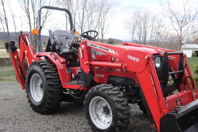 MF 1531
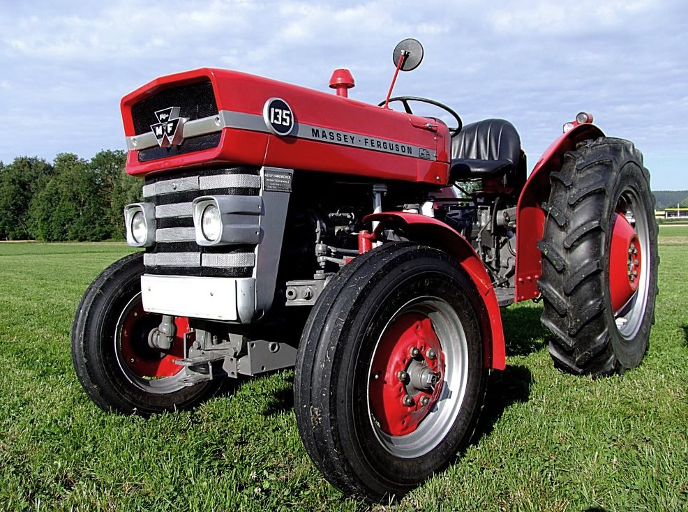 MF 135
 MF 1547
 MF 1635
________________________________________________________________________________________
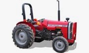 231
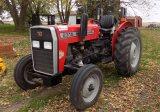 231S
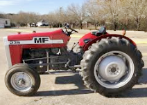 235
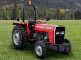 240
 241
________________________________________________________________________________________
_______________________________________________________________________________________
 255
 265
 274
 285
 375
________________________________________________________________________________________
________________________________________________________________________________________
 916X Loader
 921X Loader
 926X Loader
 931X Loader
 936X Loader
________________________________________________________________________________________
 941X Loader
 946X Loader
 951X Loader
 956X Loader
 988 Loader
________________________________________________________________________________________
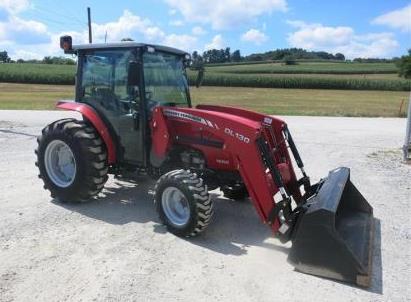 1655
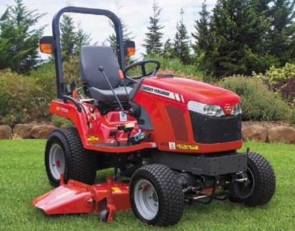 GS1705
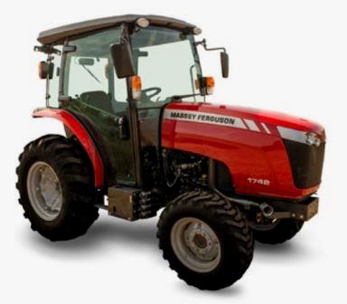 1742
 2635
 4608
________________________________________________________________________________________
 1080
 1100
 2615
 3050
 3060
________________________________________________________________________________________
 4708
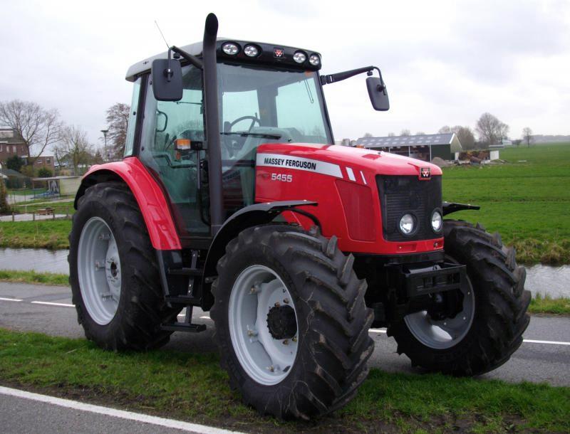 5455
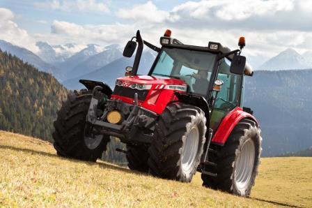 5450
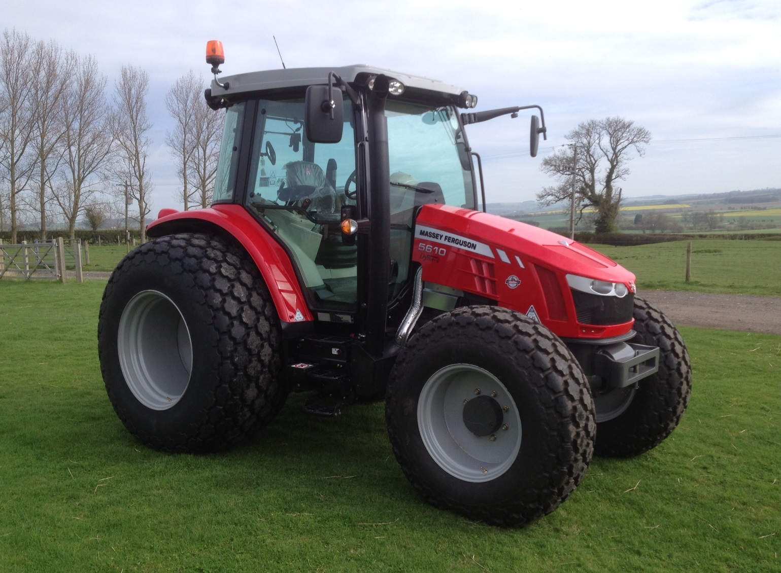 5610
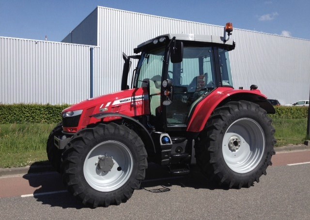 5613
________________________________________________________________________________________
 DL95 Loader
 DL100 Loader
 DL120 Loader
 DL125 Loader
 DL130 Loader
________________________________________________________________________________________
 DL135 Loader
 DL250 Loader
 DL260 Loader
 L90 Loader
 L100 Loader
________________________________________________________________________________________
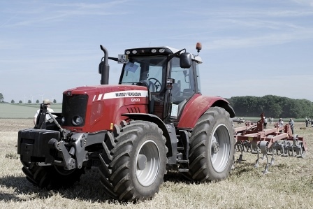 6499
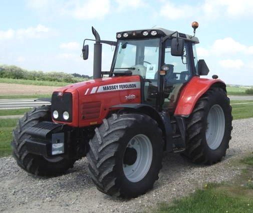 7480
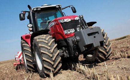 7618
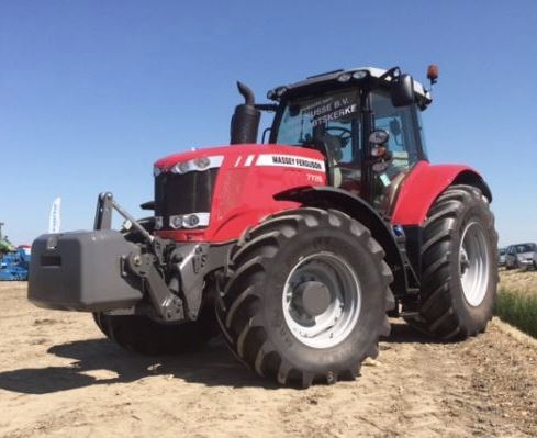 7726
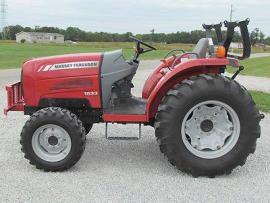 1533
________________________________________________________________________________________
 2604H
 2607H
 4455
 4610M
 4710
________________________________________________________________________________________
 L105E Loader
 L210 Loader
 1014 Loader
 1016 Loader
 1462 Loader
________________________________________________________________________________________
 1525 Loader
 1530 Loader
 232 Loader
 838 Loader
 848 Loader
________________________________________________________________________________________
 5712SL
 6713
 6715S
 7475
 7615
________________________________________________________________________________________
 7716
 7724
 8240
 8650
 8732
________________________________________________________________________________________
 246 Loader
 1036 Loader
 1038 Loader
 1080 Loader
 856 Loader