________________________________________________________________________________
Massey Ferguson 8240 tractor Powershift Gearbox
The AG150 and AG250 Powershift gearbox comprise forward and rear housings containing seven shafts and nine clutches. Six speed clutches and three range clutches.
Three clutches must be hydraulically engaged in order to transmit engine power.
These MF 8240 transmissions are fitted with their own Gerotor hydraulic pump, filter, pressure regulating valve, lubricating metering valve and nine proportional solenoid valves to engage the clutches.
These transmissions use an oil tank that is common to the gearbox and
axle assembly. The gearbox is coupled to the engine via a splined
coupling shaft situated in the transmission and a damper located on the
engine flywheel.
MF 8240 AG150 / AG250 Powershift gearbox
have the following characteristics:
- 18 forward speeds
- 6 or 8 reverse speeds
- constant meshing, helicoidal gears
- ball and roller bearings to eliminate all vibration
- common axle / gearbox oil tank
- hydraulically controlled multi-plate clutches
- electro-hydraulic gear changes
- 100% modulated gear changes
- adaptation to speed of movement
- reverse shuttle
- compact design in a 2-part housing
- housing also acts as the tractor chassis between the engine and rear
axle unit
- pressure lubrication of all clutches
- self-controlled hydraulic pump
- vibration damper in the engine flywheel
- electronically protected.
Massey Ferguson 8240 Transmission

Overall view
(1) Forward transmission housing (2) Rear transmission housing (3)
Location of the first stage shaft (4) Location of the second stage shaft
(5) Location of the third
stage shaft (6) Location of the fourth stage shaft (7) Location of the
fifth stage shaft (8) Location of the sixth stage shaft (9) Location of
the seventh stage shaft (10)
Input shaft and seal (11) 260 psi (18 bar) pressure regulating valve
(12) Clutch 2 proportional solenoid valve

Front view
(13) Clutch A proportional solenoid valve (14) Clutch R proportional
solenoid valve (15) Clutch B proportional solenoid valve (16) Clutch 1
proportional solenoid valve
(17) Clutch C proportional solenoid valve (18) Clutch L proportional
solenoid valve (19) (AG 150) clutch M proportional solenoid valve (AG
250) clutch H proportional
solenoid valve (20) (AG 150) clutch H proportional solenoid valve (AG
250) clutch M proportional solenoid valve

Top view
(21) 130 psi (9 bar) pump pressure switch (22) Engine speed sensor (23)
Forward speed sensor (24) Calibration sensor (25) Temperature sensor
(26) Clutch
hydraulic test port - 7/16” plugs (27) Lubricating pressure test port -
9/16” plugs (28) Pump hydraulic test ports - wide plugs
(29) IN port (inlet) of the pump from the tank (30) Free return to
housing port (31) Pump pressure outlet port (32) Pump pressure inlet
port to forward housing (33) Oil
outlet port towards oil cooler and lubricating relief-valve (34) Return
port for oil from oil cooler (35) Gearbox serial and model number
identification plate.

Diagramm showing the meshing of AG-150 pinions
The engine power is transmitted to the 1st stage shaft that drives the
shafts of the 2nd, 3rd and 4th stages.
The 1st stage shaft also drives the Gerotor hydraulic pump for the gearbox and acts as the PTO input shaft.
The shafts of the
2nd and 4th stages act as forward speeds with the various ratios of
input speed, while the
shaft of the 3rd stage acts as reverse with a single input speed ratio.

Diagramm showing the meshing of AG 250 pinions
This allows to obtain forward and reverse speeds. When clutch 1, 2 or R
is engaged, it locks the clutch housing to the corresponding shaft.
Each
clutch housing is
fitted with a pinion that meshes with the other shafts (all having the
same ratio), permitting the power to enter via a clutch (1, 2 or R) and
to exit via another clutch (A,
B or C) and another shaft.

Massey Ferguson 8240 Power transmission route
The various clutches supply six forward ratios and three reverse ratios
to the transmission, in accordance with the input clutches (1, 2 or R)
or output clutches (A, B
or C) selected.
The output from speed clutches directs the power to the clutch of the selected range (L, M or H), thus providing 18 forward speeds and 8 reverse speeds.
In the North American market, the electronic control does not
permit the engaging of the two highest speeds. Other international
markets may authorise
these reverse speeds in relation to the legislation in force in their
countries.
Vibration damper and coupling shafts
Tightening torque - M10 bolt (43): 68 – 92 Nm.

AG 150/AG 250 Transmission
(36) Engine flywheel (37) LUK damper (38) Bearing (39) Coupling shaft
(40) Spring (41) Input shaft seal (42) 1st stage shaft (43) Bolt

________________________________________________________________________________
 SPECS
 LOADERS
 MAINTENANCE
 PROBLEMS
________________________________________________________________________________________
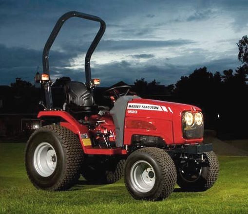 MF 1523
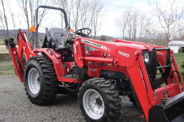 MF 1531
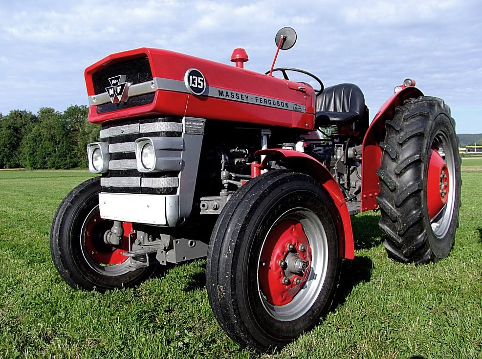 MF 135
 MF 1547
 MF 1635
________________________________________________________________________________________
 231
 231S
 235
 240
 241
________________________________________________________________________________________
_______________________________________________________________________________________
 255
 265
 274
 285
 375
________________________________________________________________________________________
________________________________________________________________________________________
 916X Loader
 921X Loader
 926X Loader
 931X Loader
 936X Loader
________________________________________________________________________________________
 941X Loader
 946X Loader
 951X Loader
 956X Loader
 988 Loader
________________________________________________________________________________________
 1655
 GS1705
 1742
 2635
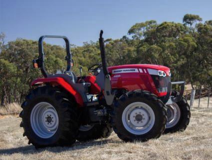 4608
________________________________________________________________________________________
 1080
 1100
 2615
 3050
 3060
________________________________________________________________________________________
 4708
 5455
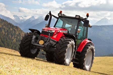 5450
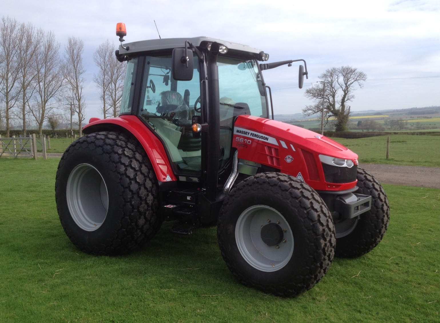 5610
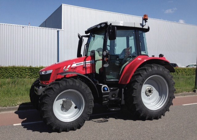 5613
________________________________________________________________________________________
 DL95 Loader
 DL100 Loader
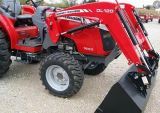 DL120 Loader
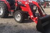 DL125 Loader
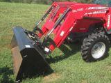 DL130 Loader
________________________________________________________________________________________
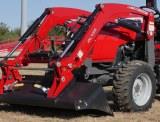 DL135 Loader
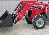 DL250 Loader
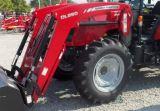 DL260 Loader
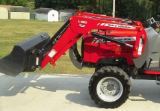 L90 Loader
 L100 Loader
________________________________________________________________________________________
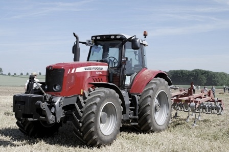 6499
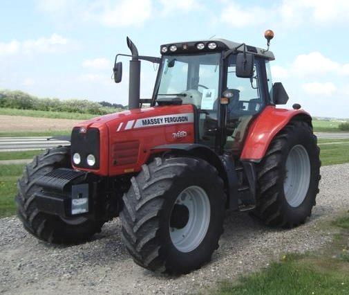 7480
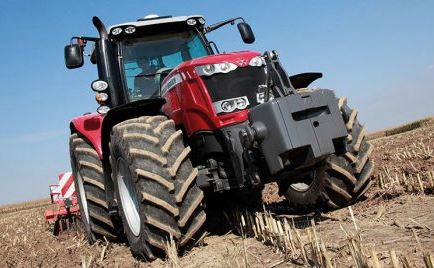 7618
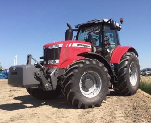 7726
 1533
________________________________________________________________________________________
 2604H
 2607H
 4455
 4610M
 4710
________________________________________________________________________________________
 L105E Loader
 L210 Loader
 1014 Loader
 1016 Loader
 1462 Loader
________________________________________________________________________________________
 1525 Loader
 1530 Loader
 232 Loader
 838 Loader
 848 Loader
________________________________________________________________________________________
 5712SL
 6713
 6715S
 7475
 7615
________________________________________________________________________________________
 7716
 7724
 8240
 8650
 8732
________________________________________________________________________________________
 246 Loader
 1036 Loader
 1038 Loader
 1080 Loader
 856 Loader