
________________________________________________________________________________
Massey Ferguson 8250, 8240 Powershift gearbox - Creeper
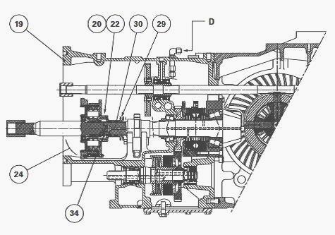
MF 8250, 8240 Tractors fitted with an AG150 or AG250 Powershift gearbox may be fitted, according to options, with a creeper. This reducer unit (24) comprises a simple epicyclical gear train having a planetary carrier and crownwheel mounted at the front of the intermediate housing (19).
It is controlled by a lever on the right-hand side console in the cab
that is linked via a cable to a link fitted on the front right-hand side
of the intermediate housing. This link moves the coupler control fork.
The coupler, fitted with straight teeth, must only be engaged when the
tractor is stationary.
Operation
The coupler (29) is integral via splines with the layshaft (30). The
moving of the control lever to the "Snail" position moves the coupler
rearwards and locks it to the planetary carrier (20) via coupler ring
(22). The speed of the output shaft is 1/4 of that of the input shaft.
Lubrication
The lubrication of the mechanical components of the epicyclical reducer
gear is ensured by an oil splash. The drive pinion and the layshaft (30)
have an axial drilled
channel, this allows flow "D" from the right-hand side hydraulic cover
to lubricate needle bearing (34).
The bearing supports the layshaft and
permits a difference in
rotation of the shafts when in the "Creeper" position.
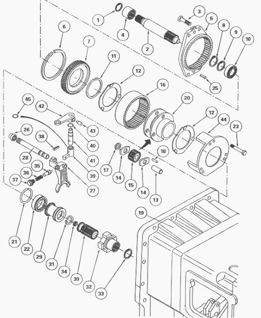
(1) Snap ring (2) Connecting shaft (3) Bolts (4) Sleeve (5) Support (6)
Snap ring (7) Bearing carrier (8) Circlip (9) Circlip (10) Ball bearing
(11) Snap ring (12) Friction
washer (13) Pin (14) Friction plates (15) Sun gears (16) Crownwheel (17)
Spacers (18) Roller bearings (19) Intermediate housing
(20) Planetary carrier (21) Snap ring (22) Coupler ring (23) Bolts (24)
Planetary carrier assembly (reducer gear) (25) Locating pin (26) Nut
(27) Fork (28) Guide rod
(29) Coupler (30) Layshaft (31) Snap ring (32) Sleeve (33) Snap ring
(34) Needle bearing (35) Locking stud (36) Spring (37) Plug (38) Pin
(39) Finger (40) O’ring (41) Pin (42) Link (43) Bolt (44) Housing (45)
Shim(s)
Removing and refitting the unit
Uncouple the Massey Ferguson 8250, 8240 tractor between the gearbox and
the intermediate housing.
Remove the sleeve (4). Remove bolts (3). Remove the shaft (2) and unit
(24) assembly.
The locating pins (25) are force fitted into the
intermediate housing (19).
Check for the presence of the locating pins on the intermediate housing.
Screw two guide studs of suitable length in the place of two bolts (3).
Place coupler (29) in contact with snap ring (31). Refit shaft (2) and unit (24) assembly turning the machined recess "E" on support (5) towards the adjusting nut (26) on guide rod (28).
Turn shaft (2) several turns to
engage the exterior splines of coupler ring (22) in those of coupler
(29).
Alternately and uniformly tighten bolts (3) lightly smeared with Loctite
241 to a torque of 90 - 120 Nm. Couple the tractor between the gearbox
and the intermediate
housing.
Disassembling, reassembling and adjusting the selection mechanism
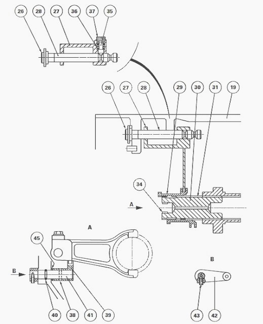
Remove unit (24). Disconnect the control cable fitted to link (42).
Disassembly
Remove plug (37). Recover spring (36) and locking stud (35).
Remove the Allen screw (43). Remove the link (42) and pin (41) fitted
with seal (40) and finger (39). Recover the shim(s) (45).
Drive out pin
(38) linking the pin and
the finger. Disengage the guide rod (28) from the fork (27) and the
intermediate housing (19). If necessary, loosen, unscrew and discard nut
(26). Remove the fork,
coupler and shaft (30) fitted with needle bearing (34).
Remove snap ring (31). If necessary, extract the bearing.
Clean and check the components. Replace any parts found to be defective.
If fitted, using an appropriate fixture, insert bearing (34) thrust against the shoulder on layshaft (30) and check that the needle bearing turns normally. Place snap ring (31). Lubricate a new seal (40) and fit it on pin (41).
Enter the pin
through the chamfered port of the intermediate housing (19).
To limit axial clearance of the pin, it is recommended to carry out
shimming with a tolerance of 0.1 mm to 0.6 mm.
Shimming
- On the pin, place an approximate thickness of shim(s) (45). Fit finger
(39) and partially fit pin (39). Reassemble the link (42) and bolt (43).
- Manually evaluate the existing clearance.
- The adjustment principle consists in obtaining a minimum clearance
between the various parts.
Action - If the clearance is outside the maximum stated tolerance,
determine a new thickness of shim(s).
After shimming, check for the correct orientation of the finger and the
link.
Definitively insert pin (38), fit and tighten Allen screw (43).
Fit the shaft, coupler and fork in
the intermediate housing. Refit the guide rod and nut assembly. Refit
the unit (24). Adjust the fork.
Couple the MF 8250, 8240 tractor between the gearbox and the
intermediate housing.
Connect the control cable and adjust it if necessary.
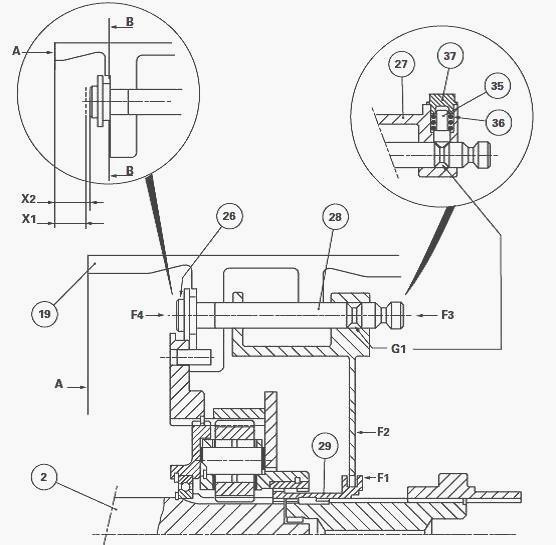
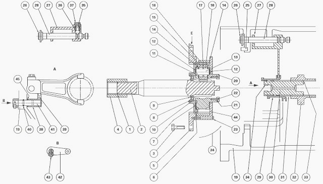
Adjustment
- Fit the locking stud (35), spring (36) and plug (38). Partially
tighten the plug.
- Position coupler (29) in accordance with F1, its forward face thrust
against shaft (2).
- Maintain the fork thrust against the coupler in accordance with F2.
Turn the guide rod (28) in nut (25) according to F3 so as to place in
contact the oblique face of
groove G1 with locking stud (35) while simultaneously holding nut (26)
against spot-faced face B of the intermediate housing (19).
- Using a depth gauge, measure X1 between the forward face of the guide
rod and face A of the intermediate housing (19).
- Hold the fork thrust against the coupler in accordance with F2.
- Turn the guide rod in the nut in accordance with F4 so as to place the
other oblique face of groove G1 in contact with the locking stud while
holding nut (26) as
previously.
- Measure X2 in the same manner as X1.
- Determine the position of adjustment X using the following formula: X
= (X1 + X2) : 2
- Provisionally position guide rod (28) to dimension X.
- Place coupler (29) in the "Creeper unit" position. Manually check for
locking of the control and the clearance between the fork and the
coupler.
- If this check is satisfactory, remove unit (24), plug (37), the spring
and the locking stud.
- Grease the threads of the guide rod and the threads of nut (26).
- Tighten the nut, previously lightly smeared with Loctite frein filet
faibe, and definitively position the guide rod according to the
previously calculated dimension X.
- Lock the nut by bending its collar into the machined groove of the
guide rod.
- Reassemble the locking mechanism. Tighten plug (37) to a torque of 50
- 70 Nm. Refit unit (24).
Disassembling and reassembling the epicyclical reducer gear
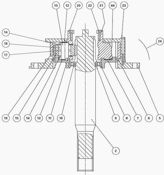
Remove unit (24). Take out bolts (23). Remove housing (44). Disengage
reducer gear (20) from shaft (2). Remove crownwheel (16). Separate
supports (5) (7). If
necessary, take off snap ring (6) and circlips (8) (9).
Extract bearing
(10). Remove the friction washers (12). Take off circlip (11). Drive out
pins (13). Remove sun
gears (15) taking care not to lose the needle bearings (18), spacers
(17) and the friction plates (14).
The coupler ring (22) is fitted in the planetary carrier using a press.
Snap ring (21) provides additional locking of the various parts.Check and clean the components. Replace any parts found to be defective.
Fit each sun gear (15) with both needle bearings (18) and spacer (17) smeared with miscible grease. Refit the sun gears and position the friction plates (14).
Refit pins (13) correctly turning the spot-face for the fitting of snap ring (11). Fit the snap ring. Manually check the axial clearance and rotation of each sun gear.
Lightly smear the faces of the reducer gear with miscible grease and fit the friction washers (12), with the tabs lodged in the appropriate grooves. If disassembled, insert bearing (10) on shaft (2) using an appropriate fixture.
Fit circlips (8)
(9) and snap ring (6). Assemble supports (5) (7). Engage reducer gear
(20) on shaft (2). Refit the
crownwheel (16).
Position housing (44), with the cut out turned downward. Assemble and
tighten bolts (23) previously lightly smeared with Loctite 241 and
tighten to a torque of 10 -
14 Nm. Refit unit (24).
Adjusting the control
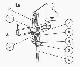
On lever "A"
Place control lever "A" in the "Snail" position. Screw yoke (1) flush
with the end of the threaded part of the cable (6). Fit the yoke (1) on
to lever "A" with clip (7).
Tighten nut (2). Tighten nut (3) against sheath end (5).
Fit the sheath end and Grower washer on to the support. Tighten nut (4)
checking that the cable is not pinched.
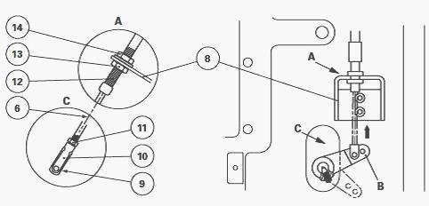
On link "B"
Place link "B" in the "Creeper" position (coupler (29) locked by splines
to planetary carrier (20) fork locked). Screw yoke (9) flush with the
threaded part of cable (6).
Assemble yoke (9) on to link "B" using clip (10). Tighten nut (11). Adjust stop (12) using nut (13) on support (8) while checking that link "B" is still correctly locked.
Tighten nut (14) and check that the cable is not pinched. Check for correct operation and locking of the control in the “Direct drive” position.
________________________________________________________________________________
________________________________________________________________________________________
 SPECS
SPECS LOADERS
 MAINTENANCE
 PROBLEMS
________________________________________________________________________________________
 MF 1523
 MF 1531
 MF 135
 MF 1547
 MF 1635
________________________________________________________________________________________
________________________________________________________________________________________
 231
231 231S
231S 235
235 240
240 241
241________________________________________________________________________________________
 255
255 265
265 274
274 285
285 375
375________________________________________________________________________________________
________________________________________________________________________________________
 916X Loader
 921X Loader
 926X Loader
 931X Loader
 936X Loader
________________________________________________________________________________________
 941X Loader
 946X Loader
 951X Loader
 956X Loader
 988 Loader
________________________________________________________________________________________
 1655
1655 GS1705
 1742
1742 2635
2635 4608
4608________________________________________________________________________________________
 1080
1080 1100
1100 2615
2615 3050
3050 3060
3060________________________________________________________________________________________
 4708
4708 5455
5455 5450
5450 5610
5610 5613
5613________________________________________________________________________________________
 DL95 Loader
 DL100 Loader
 DL120 Loader
 DL125 Loader
 DL130 Loader
________________________________________________________________________________________
 DL135 Loader
 DL250 Loader
 DL260 Loader
 L90 Loader
 L100 Loader
________________________________________________________________________________________
 6499
6499 7480
7480 7618
7618 7726
7726 1533
1533________________________________________________________________________________________
 2604H
2604H 2607H
2607H 4455
4455 4610M
4610M 4710
4710________________________________________________________________________________________
 L105E Loader
 L210 Loader
 1014 Loader
 1016 Loader
 1462 Loader
________________________________________________________________________________________
 1525 Loader
 1530 Loader
 232 Loader
 838 Loader
 848 Loader
________________________________________________________________________________________
 5712SL
 6713
6713 6715S
6715S 7475
7475 7615
7615________________________________________________________________________________________
 7716
7716 7724
7724 8240
8240 8650
8650 8732
8732________________________________________________________________________________________
 246 Loader
 1036 Loader
 1038 Loader
 1080 Loader
 856 Loader