
________________________________________________________________________________
Massey Ferguson 8260, 8270 Power Shuttle gearbox - Removing and install the front Clutch
Split the Massey Ferguson 8260, 8270 tractor between the engine and the
gearbox. Drain the gearbox and the centre housing. Remove the clutch
cover plate from the gearbox.
Remove the flange from each end of the pipe (78) and remove it.
Remove pipes (31) (74) (86) (87) and (94).
Remove the front clutch (2) and pull it from the housing using a locally
made tool.
Clean the parts. Replace any defective ones.
Check that PTO shaft (1) is installed.
Refit the clutch using the tool used for removal.
Replace the pipe seals (74) (94).
Install the pipes, carry out operation 5 in reverse order. Replace the
pipe seals (78) and refit them the pipe. Tighten the flange holding
screw at each end of the pipe to a torque of 25 Nm - 35 Nm.
Install the gearbox clutch cover plate. Top up the housing oil level and check it with the sight glass located at the rear left of the centre housing.
Couple the MF 8260, 8270 tractor between the engine and the gearbox.
Carry out a road test using the power shuttle and using ratios A, B, C
and D of the Dynashift. Check oil tightness of the mating faces and
hydraulic unions.
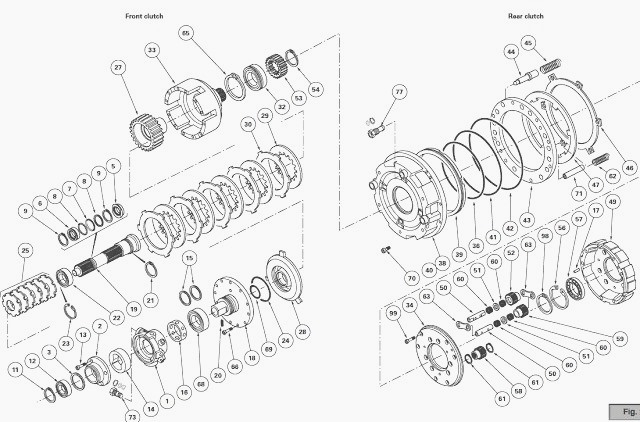
Disassembling and reassembling the MF 8270,
8260 front clutch
Separate cover (33) from unit (18). Remove the discs (29) and the
intermediate plates (30).
Remove the front snap ring (9). Remove the splined ring (6), the
anti-extrusion rings (8) and seal (7).
Remove circlip (11), take off cover (2) from the pump (14) complete with
bearing (12).
Pull the lubricating pump out of the pump unit (1) and take it apart
from the clutch housing (18).
Remove seal rings (15). If necessary, extract ring (16) and remove the
1.5 bar valve (73).
Place the partially disassembled clutch on a suitable locally made
fixture.
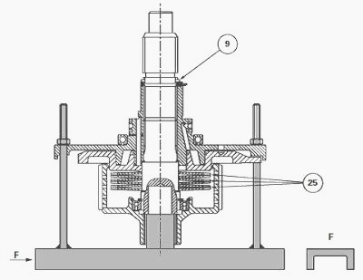
Compress the Belleville washers (25) and remove the rear snap ring (9).
Remove locking ring (5). Gradually release the Belleville washers.
Split unit (18) fitted with piston (28) from shaft (19).
Remove the Belleville washers.
Remove snap ring (23). Pull out the shaft (19) complete with bearing
(22) from hub (27).
Remove the circlip (21). Extract the bearing (22) from shaft (19).
Remove the piston. Remove seals (24) (69) and discard them. If
necessary, extract the bearing (68) from unit (18).
If necessary, remove snap ring (54) and remove the input sun gear (53).
Remove snap ring (65). Extract bearing (32).
Make sure that pin (20) is fitted.
If removed, fit the bearing (32) on cover (33), using a press and a
suitable tool. Install snap ring (65).
If disassembled, refit bearing (68).
Lubricate the new seals (24) (69) and fit them on the piston. Fitting piston (28). The angular position of the piston depends on the position of unit (18) lubricating ports. Align the indexing holes drilled in the unit and the piston. To align, use a pin of a suitable diameter.
Complete the installation of the piston by
gradually and alternately striking around its top rim with a plastic
mallet. Check that there are no fragments of the seal after assembly.
Using a suitable tool, force fit bearing (22) on shaft (19), the seal
side facing towards the rear clutch. Fit circlip (21).
Put the assembly (shaft, bearing, circlip) in the hub (27). Fit the snap
ring (23).
Install the Belleville washers.
Massey Ferguson 8270, 8260 Tractors can be fitted with six Belleville washers. Assemble unit (18) fitted with the piston (28) on shaft (19). Compress the Belleville washers using the tool.
Position ring (5),
aligning two of the flats with the flats on unit (18). Replace the rear
snap ring (9) and correctly
position it in the bottom of the groove.
Remove the fixture.
Check that the seal rings (15) turn freely in their grooves. Fit the
seal rings, lightly coated with miscible grease, making sure that they
do not protrude beyond the rim
of unit (18).
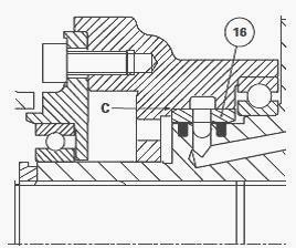
If necessary, fit the 1.5 bar valve (73) and tighten to a torque of 47 -
54 Nm. Insert ring (16) using a suitable fixture, with the chamfer “C”
in the direction.
Lubricate the bush. Assemble pump unit (1) on unit (18).
Lubricate pump (14) with transmission oil and position it aligning the
flats of the rotor with those on the unit (18).
Manually check the angular movement of the rotor on the flats of unit
(18).
Install bearing (12) on cover (2) of the pump. Install the cover.
Install circlip (11) and screws (13) and tighten to a torque of 36 - 46
Nm.
Lubricate and install a new assembly (O’ring (7) and anti-extrusion ring (8)). Slide on the splined bush (6). Install a new front snap ring (9). Soak the discs (29) in a transmission oil bath for approximately 1 hour.
Check that they are correctly saturated.
Position the intermediate plates (30), aligning the tabs and the discs
(29) on hub (27) according to the type of tractor.
Lightly smear the mating face of the clutch cover (33) on the unit (18) with Loctite 549 or its equivalent. Place the cover on the unit, the tabs of the intermediate plates lodged in the cut out notches on the clutch cover.
Fit and
tighten screws (66) to 25.5 - 34.5 Nm.
Manually check the rotation of the hub (27).
If necessary, refit the input sun gear (53) and fit snap ring (54).
Shimming the MF 8260, 8270 front clutch
This operation consists in obtaining an axial clearance of 0.60 to 0.80
mm between the pump cover (2) and clutch cover plate (4).
To carry out this operation, remove the PTO shaft so as to remove the
effect of the spring fitted at the rear end of the shaft to alow the
clutch assembly to move.
Install the clutch on cover (38) of the rear clutch.
Place a approx. thick 2 mm shim (3) on cover (2). Lubricate the lip of the cover plate seal . Protect the lip of the seal by fitting a protective material over the splines of the shaft (19).
Fit
two guide studs on opposite
sides of the gearbox housing and temporarily install the clutch cover
plate (4) without using Loctite. Gradually tighten several screws.
Place a dial gauge at the end of shaft (19) and check the clearance by
moving the shaft sideways.
Check that the snap ring (65) of bearing (32) is correctly in contact
with cover (38) by pushing the shaft (19) back as far as possible.
Remove clutch cover plate (4). Depending on the reading previously obtained with the dial gauge, define a new thickness for shim(s) (3) in order to obtain a clearance of between 0.60 mm and 0.80 mm.
________________________________________________________________________________
________________________________________________________________________________________
 SPECS
SPECS LOADERS
 MAINTENANCE
 PROBLEMS
________________________________________________________________________________________
 MF 1523
 MF 1531
 MF 135
 MF 1547
 MF 1635
________________________________________________________________________________________
________________________________________________________________________________________
 231
231 231S
231S 235
235 240
240 241
241________________________________________________________________________________________
 255
255 265
265 274
274 285
285 375
375________________________________________________________________________________________
________________________________________________________________________________________
 916X Loader
 921X Loader
 926X Loader
 931X Loader
 936X Loader
________________________________________________________________________________________
 941X Loader
 946X Loader
 951X Loader
 956X Loader
 988 Loader
________________________________________________________________________________________
 1655
1655 GS1705
 1742
1742 2635
2635 4608
4608________________________________________________________________________________________
 1080
1080 1100
1100 2615
2615 3050
3050 3060
3060________________________________________________________________________________________
 4708
4708 5455
5455 5450
5450 5610
5610 5613
5613________________________________________________________________________________________
 DL95 Loader
 DL100 Loader
 DL120 Loader
 DL125 Loader
 DL130 Loader
________________________________________________________________________________________
 DL135 Loader
 DL250 Loader
 DL260 Loader
 L90 Loader
 L100 Loader
________________________________________________________________________________________
 6499
6499 7480
7480 7618
7618 7726
7726 1533
1533________________________________________________________________________________________
 2604H
2604H 2607H
2607H 4455
4455 4610M
4610M 4710
4710________________________________________________________________________________________
 L105E Loader
 L210 Loader
 1014 Loader
 1016 Loader
 1462 Loader
________________________________________________________________________________________
 1525 Loader
 1530 Loader
 232 Loader
 838 Loader
 848 Loader
________________________________________________________________________________________
 5712SL
 6713
6713 6715S
6715S 7475
7475 7615
7615________________________________________________________________________________________
 7716
7716 7724
7724 8240
8240 8650
8650 8732
8732________________________________________________________________________________________
 246 Loader
 1036 Loader
 1038 Loader
 1080 Loader
 856 Loader