
________________________________________________________________________________
Massey Ferguson 8280 gearbox with Power Shuttle – Mainshaft
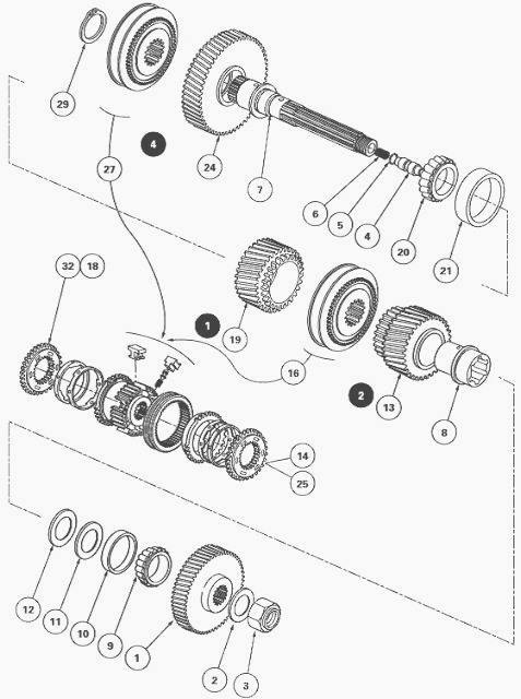
The mainshaft (7) fitted to MF 8280 heavy gearboxes with a power shuttle rotates on two taper roller bearings (9) (10) and (20) (21) lying in the two lower bearing blocks of the main gearbox.
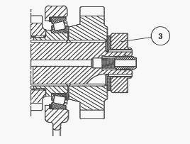
The input pinion (1), fitted at the front, is integral with the shaft via splines. It is held by washer (2) and nut (3).
Between the two lower bearing blocks, the shaft holds the driving pinions of 2nd (13) and 1st (19) that run free, as well as the synchromesh assembly for 1st and 2nd, the hub of which is splined to the shaft.
At the rear the shaft holds the 4th gear driving pinion (24) that runs free and the synchromesh assembly for 3rd and 4th gear. The synchromesh is of the double cone type.
The rear bore receives bearing cup (22) of the taper roller bearing of
the output shaft. The lubrication of the 1st gear
pinion and 2nd gear bush is ensured by a central channel with radial
ports.
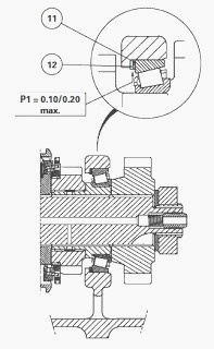
The pre-loading of bearings is adjusted by means of shim(s) (11) placed
behind bearing cup (10).
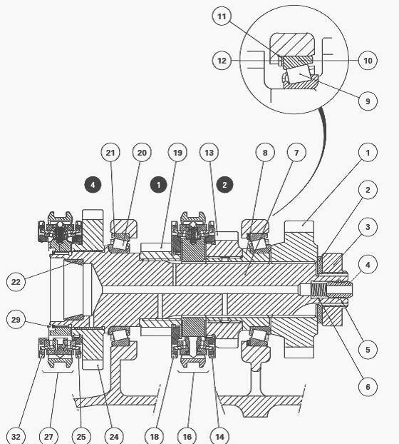
(1) Input pinion (2) Tab washer (3) Nut (4) Lubricating pipe (5) Snap
ring (6) Spring (7) Mainshaft (8) Bush (9) Bearing cone (10) Bearing cup
(11) Shim(s) (12) Spacer (13) 2nd gear driving pinion (14) 2nd gear
synchromesh cone (16) 1st and 2nd gear synchromesh (18) 1st gear
synchromesh cone (19) 1st gear driving pinion (20) Bearing cone (21)
Bearing cup (22) Bearing cup (24) 4th gear driving pinion (25) 4th gear
synchromesh cone (27) 3rd and 4th gear synchromesh (29) Snap ring (32)
3rd gear synchromesh cone.
To take out the mainshaft, it is necessary to remove the gearbox.
Uncouple the Massey Ferguson 8280 tractor between the gearbox and the
intermediate housing.
Separate the gearbox from the engine. Remove the selector cover. Place
the gearbox on a suitable fixture.
Take off the input unit. Remove the selector rails and forks. Remove the
output shaft.
Disassembling and reassembling the shaft
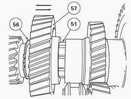
To remove the synchromesh (27) and 4th gear driving pinion (24), it is
necessary to remove circlip (56) from the machined groove of layshaft
(51). Then, push
back the pinion (57).
Take off snap ring (29). Remove the 3rd and 4th gear synchromesh (27),
carefully marking its position.
Remove the synchromesh parts (rings, cones and bushes) carefully marking
their locations if the pinion (24) is to be reused later.
Immobilise the shaft using a locally made tool using a MF 8280 4 WD
clutch plate.
If necessary, remove lubricating pipe (4) and spring (6).
Completely unscrew nut (3) (60 mm flat) using socket.
Remove tab washer (2) and the input pinion (1).
Take out bush (8) complete with bearing cone (9).
Remove the tool. Take the shaft out of the housing complete with the 1st
gear driving pinion (19) towards the rear via the bearing block opening,
while holding
together the 1st and 2nd synchromesh, pinion and fork assembly.
The extraction of the 1st and 2nd gear fork from the housing is carried
out along with the synchromesh assembly (16) and the 2nd gear driving
pinion (13).
Remove the complete assembly (synchromesh, 2nd gear pinion and fork)
through the selector cover opening.
Take out bearing cups (10) (21).
Carefully match the cups and cones if they are to be re-used.
Remove the shim(s) (11) and spacer (12).
If necessary, extract bearing cones (9) (20) and bearing cup (22). Take
off snap ring (5).
Clean and check the parts, discard any defective ones.
Ensure that the central and radial lubricating channels of shaft (7) are
not blocked.
If removed, using a press and a suitable fixture, insert the bearing
cones (9) (20) on bush (8) and shaft (7). On the latter, also position
snap ring (5) and insert cup
(22).
Lubricate the bearing cups and cones. Install bearing cup (21).
Check for wear on synchromesh parts of 1st and 2nd gear.
Outside the housing, assemble the 2nd gear pinion (13), new synchromesh
parts and 1st and 2nd gear synchromesh.
If the synchromesh parts are to be re-used, refit each part in its
initial position, as marked during disassembly.
Between the two compartments, refit the complete assembly with the 1st
and 2nd gear fork correctly positioned.
Slide the shaft and 1st gear pinion (19) through the rear of the housing while holding the pinion / synchromesh assembly. Shim the shaft. Install pinion (1). Degrease the threaded end of the shaft using solvent.
Hold the shaft as
desribed in operation. Clean and lightly smear the new nut (3) with
Loctite 270 or equivalent
then tighten it to a torque of 130 - 170 Nm using the socket previously
used.
Lock the nut by bending its collar, without breaking it, into the
grooves of the shaft using a suitable drift. Manually check the rotation
of the shaft.
If removed, fit spring (6) and lubricating pipe (4) in shaft (7).
Check the wear of the 3rd and 4th gear synchromesh parts. Install the synchromesh parts that are being re-used, according to the markings made during disassembly.
Position the driving pinion of 4th
gear (24) and the
synchromesh of 3rd - 4th (27).
Move forward pinion (57) on the mainshaft. Install circlip (56) in its
throat without bending it, and ensuring that it is correctly positioned.
Place snap ring (29).
Manually check:
- the axial clearance of the pinions
- the rotation of the shaft and its pinions.
Reassemble the output shaft.
Install the input unit.
Reassemble the selector rails. Adjust the 1st - 2nd and Hare / Tortoise
forks and selectors.
Install the selector cover. Check that the gear shifting operates
correctly and also check for the presence of the Hare / Tortoise
position.
Connect the gearbox with the engine.
Couple the Massey Ferguson 8280 tractor to the gearbox and the
intermediate housing.
Check the oil tightness of mating faces and hydraulic unions.
Carry out a road test of the Power Shuttle, gears, Hare / Tortoise range
and A, B, C and D ratios of the Dynashift.
Shimming the shaft
Determine the thickness of shim(s) (11) required to obtain a provisional
clearance of 0.10 to 0.15 mm for the later loading of the bearings.
Reminder: It is essential to place spacer (12) against the housing, the
previously determined shim(s) (11) and bearing cup (10).
Slide bush (8) fitted with cone (9) and pinion (1) onto shaft (7).
Install washer (2) and nut (3).
Place the locking tool on the shaft, tighten the nut to a torque of 130
- 170 Nm and remove the tool.
Shimming
Place the finger of the dial gauge on the end of the shaft (7). From the
front of the housing, pull hard on the shaft, turning alternately from
left to right to correctly seat
the cones in their bearing cups.
Set the dial gauge to zero.
In relation to the clearance measured, select a definitive thickness for
shim (11) in order to provide a pre-loading of : P1 = 0.10 to 0.20 mm
maximum.
Preferably shim to the maximum tolerance.
Place the locking tool on the shaft, loosen nut (3) and take off the
pinion (1).Take off bush (8) complete with bearing cone (9) from shaft (7).
Remove bearing cup (10) from the housing. Place shims (11) selected during operation 56 between spacer (12) and bearing cup (10). Slide the bush (8) and cone (9) assembly onto shaft (7). Proceed with the reassembly phase.
________________________________________________________________________________
________________________________________________________________________________________
 SPECS
SPECS LOADERS
 MAINTENANCE
 PROBLEMS
________________________________________________________________________________________
 MF 1523
 MF 1531
 MF 135
 MF 1547
 MF 1635
________________________________________________________________________________________
________________________________________________________________________________________
 231
231 231S
231S 235
235 240
240 241
241________________________________________________________________________________________
 255
255 265
265 274
274 285
285 375
375________________________________________________________________________________________
________________________________________________________________________________________
 916X Loader
 921X Loader
 926X Loader
 931X Loader
 936X Loader
________________________________________________________________________________________
 941X Loader
 946X Loader
 951X Loader
 956X Loader
 988 Loader
________________________________________________________________________________________
 1655
1655 GS1705
 1742
1742 2635
2635 4608
4608________________________________________________________________________________________
 1080
1080 1100
1100 2615
2615 3050
3050 3060
3060________________________________________________________________________________________
 4708
4708 5455
5455 5450
5450 5610
5610 5613
5613________________________________________________________________________________________
 DL95 Loader
 DL100 Loader
 DL120 Loader
 DL125 Loader
 DL130 Loader
________________________________________________________________________________________
 DL135 Loader
 DL250 Loader
 DL260 Loader
 L90 Loader
 L100 Loader
________________________________________________________________________________________
 6499
6499 7480
7480 7618
7618 7726
7726 1533
1533________________________________________________________________________________________
 2604H
2604H 2607H
2607H 4455
4455 4610M
4610M 4710
4710________________________________________________________________________________________
 L105E Loader
 L210 Loader
 1014 Loader
 1016 Loader
 1462 Loader
________________________________________________________________________________________
 1525 Loader
 1530 Loader
 232 Loader
 838 Loader
 848 Loader
________________________________________________________________________________________
 5712SL
 6713
6713 6715S
6715S 7475
7475 7615
7615________________________________________________________________________________________
 7716
7716 7724
7724 8240
8240 8650
8650 8732
8732________________________________________________________________________________________
 246 Loader
 1036 Loader
 1038 Loader
 1080 Loader
 856 Loader