
________________________________________________________________________________
Massey Ferguson 8250 Power Shuttle gearbox - Removing and install the rear clutch
Remove the MF 8250 front clutch. Remove the input unit.
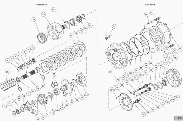
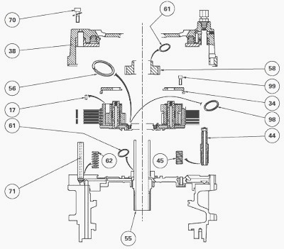
Remove the screws (70) and remove the cover (38).
Recover the spools (44) and the springs (45)
Remove the thick springs (62) and the pins (71).
On cover (38), remove:
- the plate (43)
- the seal (42) and discard it
- the piston (39)
- the seals (36) (41) and discard them
- the unions (72), the 13 bar valve (77) and seal (75) on the 17 bar
supply port.
Immobilise planet carrier (49).
Remove screws (99) securing the cover (34) and remove it.
Remove the discs (47) and the intermediate plates (46).
Separate the output sun gear (58), held by the snap rings (61), from the
primary shaft (55).
Remove snap ring (98).
Remove the planet carrier (49) with the double and single pinion gears
(52) (59).
On the planet carrier (49), remove:
- the plates (63)
- the double pinion gears (52) and the pins (50). Note and mark their
location.
- the single pinion gears (59) and pins (50). Note and mark their
location.
- the snap ring (56) and bearing (57).
- rotation of pinion gears around the pins (50) is on two rows of needle
bearings (60), joined and separated by a spacer (51).
- if the pinion gears and the pins are to be removed, check that no
unwanted needle or spacer remains in the planet carrier after refitting.
Clean and check all parts. Replace any defective ones.
Check that the ports in the pinion gear pins and the channels in the
planet carriers are not clogged.
Where necessary, fit the pinion gears with two rows of needle bearings
coated with miscible grease and separated by a spacer.
On the planet carrier, refit:
- bearing (57) and position snap ring (56),
- the double and single pinion gears (52) (59) positioned,
- pins (50), with the lubricating ports placed facing those in the
planet carrier (49).
Each end of the pins (50) contains:
- a port, one of which is closed off by a rivet (35) while the other is
used for pinion gear lubrication,
- a flat and a shoulder that stop any pin rotation or any side movement.
Install the partially assembled planet carrier. Fit the snap ring (98)
and the rear snap ring (61) on the output sun gear (58).
Position marks "R" (punch marks) on the double pinion gears (52) so that
they pass through a centerline meeting at "O".
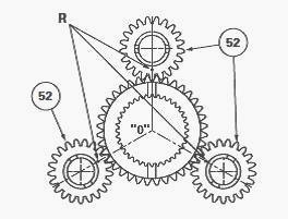
The mark on the front side of the planet carrier corresponds to the
alignment of the two splines. It is mandatory to respect these positions
of the punch marks during
assembly of the output sun gear (58).
Slide the output sun gear (58), correctly oriented, on to the primary
shaft (55), making sure that the punch marks of each pinion gear remain
in the required position.
Install the front snap ring (61).
Soak the discs (47) in a Massey Ferguson 8250 transmission oil bath for
approximately 1 hour. Check that they are correctly saturated.
Install the discs (47) and the intermediate plates (46) depending on the type of tractor. Check that the centering pin (17) is fitted. Install cover (34).
Check that it is correctly positioned on the pins
(50) of the pinion gears and in the centering pin.
Immobilise the planet carrier, using the same method as used during
disassembly.
Fit and tighten screws (99) to a torque of 36 - 46 Nm with the threads
previously lightly smeared with Loctite 242 or equivalent.
On cover (38), check for the presence of rivets (40) at the end of the
channels and refit:
- piston (39) with new lubricated seals (36) (41), gradually and
alternately striking around the piston rim with a plastic mallet. Check
that no fragments of the seal
remain after assembly,
- plate (43) with a new lubricated seal (42), aligning the holes of the
plate with those in the cover (38).
Insert the plate using the same method as used for piston (39).
The thickness of the plate (43) differs according to the number of discs
and intermediate plates.
Refit pins (71) and springs (62) in their respective locations on the input unit. Coat the spools (44) and the springs (45) with miscible grease.
Fit and
stick the spools in each compartment of cover (38), with the points
towards the unions (72).
Slide and stick a spring (45) in each spool.
On the outside face of the cover (38), place three sufficiently long and
equally spaced studs in the holes provided for screws (64).
Install and position the cover, with the 13 bar valve port (77) turned
upwards.
Before fitting screws (70), check that the spools (44) slide freely in
each compartment of the front cover on the input unit.
To do this,
compress the springs (45),
using a screwdriver passed through the tapped holes of the unions (72).
If the springs cannot be compressed, it is important to find the reason.
Pre-tighten screws (70).
During pre-tightening, check that the spools (44) still slide freely.
Also check that each end of the springs (62) are correctly housed in
their bases.
Definitively tighten the screws (70) to a torque of 29 - 37 Nm. After
completing the tightening, check the sliding movement again and return
of each spool to its initial
position.
A spool that is blocked open may limit or interrupt lubrication to the
Massey Ferguson 8250 front clutch.
Install the 13 bar valve (77) with its seal on cover (38) and tighten to
a torque of 12.5 Nm - 13.5 Nm maximum. Fit and tighten the unions (72).
Install the input unit and the front clutch.
Disassembling and reassembling the driving pinion - Shimming the shaft
The rearward position of the Dynashift, caused by the presence of the
rear shuttle clutch in the housing of the unit, limits the space
available at the rear of the input
unit. This is why the secondary shaft (1) and the pinion (2) are
machined as a single component.
Remove the MF 8250 tractor front clutch. Remove the input unit. Remove
the rear clutch. Remove the Dynashift device.
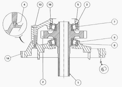
Pair bearing cones and bearing cups together if they are to be re-used.
Remove screws (13) and casing (5). Recover the locating pin (4).
Where necessary, remove bearing cup (16) and shims (3).
Take out the secondary shaft (1), pinion and bearing cones (7) (9)
assembly from cover (14).
Remove bearing cup (8).
Where needed, separate the bearing cones from the shaft.
Drive out the roller bearing (1), the gearbox front intermediary shaft
support.
Take off oil deflector (2) and discard it if necessary.
Check that the ports of the secondary shaft are not clogged and check
for the presence of lubrication restrictor "R"
Clean and check parts. Replace any defective ones.
Lubricate the bearing cones and cups with MF 8250 transmission oil
before assembly.
Insert bearing cones (7) (9) in contact with pinion (2) using a suitable
press and fixture.
Place the bearing cup (8) in cover (14).
Install the secondary shaft (1), pinion and bearing cones assembly
inside the cover.
Shimming
Determine the thickness of shims (3) required in order to obtain a
temporary clearance of 0.10 mm to 0.15 mm approximately.
Place the previously determined shims in casing (5) followed by the
bearing cup (16).
Place the locating pin (4) and the unit on cover (14). Tighten screws
(13) to a torque of 29 - 37 Nm.
Place the unit in a vice with jaw protectors, and carry out a definitive
shimming of the shaft.
Shimming the shaft (1).
The principle consists in determining a thickness of shims (3) to fit
between the bearing cup of bearing (16) and casing (5).
It is recommended to remove oil deflector (2) in order to avoid any
interference between it and the shaft (1).
Position the feeler of the dial gauge on the end of the shaft.
Pull hard on shaft (1), alternately turning it from left to right in
order to correctly seat the cones in the bearing cups.
Set the needle of the dial gauge to zero.
Repeat operation 118 this time while pushing.
Depending on the clearance measured, select a new shim thickness (3) to
provide a preloading of: P1 = 0.05 mm to 0.15 mm - Where possible, shim
to the
maximum tolerance.
Remove screws (13). Remove casing (5).
Position the definitive shims (3) selected during along with bearing cup
(16) in the casing (5).
Install the casing, shim(s) and bearing cup assembly on cover 14, first
checking for the presence of locating pin (4).
Fit and definitively tighten screws (13) to a torque of 29 - 37 Nm, the
threads previously smeared with Loctite 242 or equivalent.
Manually check the rotation of the shaft.
Turn the oil deflector (2) and insert the roller bearing (1) in thrust against the unit housing. Install the Dynashift device. Install the rear clutch. Install the input unit. Install the front clutch.
________________________________________________________________________________
________________________________________________________________________________________
 SPECS
SPECS LOADERS
 MAINTENANCE
 PROBLEMS
________________________________________________________________________________________
 MF 1523
 MF 1531
 MF 135
 MF 1547
 MF 1635
________________________________________________________________________________________
________________________________________________________________________________________
 231
231 231S
231S 235
235 240
240 241
241________________________________________________________________________________________
 255
255 265
265 274
274 285
285 375
375________________________________________________________________________________________
________________________________________________________________________________________
 916X Loader
 921X Loader
 926X Loader
 931X Loader
 936X Loader
________________________________________________________________________________________
 941X Loader
 946X Loader
 951X Loader
 956X Loader
 988 Loader
________________________________________________________________________________________
 1655
1655 GS1705
 1742
1742 2635
2635 4608
4608________________________________________________________________________________________
 1080
1080 1100
1100 2615
2615 3050
3050 3060
3060________________________________________________________________________________________
 4708
4708 5455
5455 5450
5450 5610
5610 5613
5613________________________________________________________________________________________
 DL95 Loader
 DL100 Loader
 DL120 Loader
 DL125 Loader
 DL130 Loader
________________________________________________________________________________________
 DL135 Loader
 DL250 Loader
 DL260 Loader
 L90 Loader
 L100 Loader
________________________________________________________________________________________
 6499
6499 7480
7480 7618
7618 7726
7726 1533
1533________________________________________________________________________________________
 2604H
2604H 2607H
2607H 4455
4455 4610M
4610M 4710
4710________________________________________________________________________________________
 L105E Loader
 L210 Loader
 1014 Loader
 1016 Loader
 1462 Loader
________________________________________________________________________________________
 1525 Loader
 1530 Loader
 232 Loader
 838 Loader
 848 Loader
________________________________________________________________________________________
 5712SL
 6713
6713 6715S
6715S 7475
7475 7615
7615________________________________________________________________________________________
 7716
7716 7724
7724 8240
8240 8650
8650 8732
8732________________________________________________________________________________________
 246 Loader
 1036 Loader
 1038 Loader
 1080 Loader
 856 Loader