________________________________________________________________________________
Massey Ferguson 8730, 8737 hydraulic system - Disassembling and reassembling the pumps
The Massey Ferguson 8730, 8737 hydraulic steering pump is fitted at the end of the variable displacement pump. It is a 19cc fixed displacement pump, with a 120 bar maximum pressure and a gear ratio of 67/58.
It is fitted to the variable displacement pump by two CHC M8 screws. It
rotates around a coupling sleeve. The
variable displacement pump has maximum capacity of 60cc, and a 400 bar
maximum pressure.
The gear ratio is 67/58. Drive is transmitted directly to the gearbox by a gear train. The pump is fitted to the gearbox housing by two HM 12 screws.
The lubricating pump is a fixed displacement pump. It is a gear pump and
is fitted to the same drive pinion as the service pump. It’s capacity is
23.4cc.
Disassembling the steering pump and the
variable displacement pump
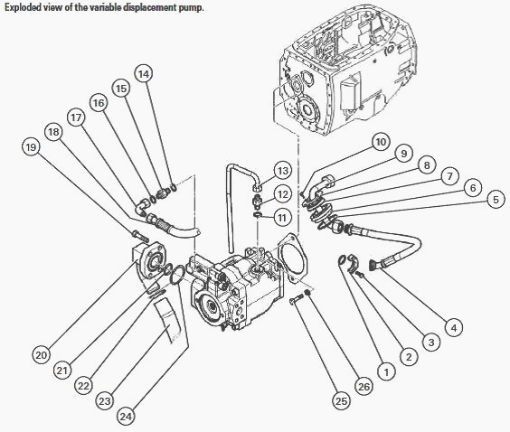
variable displacement pump
1 - O’ring, 2 – Flange, 3 – Screw, 4 – Hose, 5 – Gasket, 6 – Plug, 7 -
O’ring, 8 – Washer, 9 - Rigid pipe,10 – Screw, 11 - O’ring, 12 – Union,
13 - Rigid pipe, 14 -
O’ring,15 – Union,16 - O’ring,17 - Elbow union,
18 – Hose,19 – Screw, 20 – Flange, 21 - O’ring, 22 – Collar, 23 – Hose,
24 - O’ring, 25 – Screw, 26 - Washer
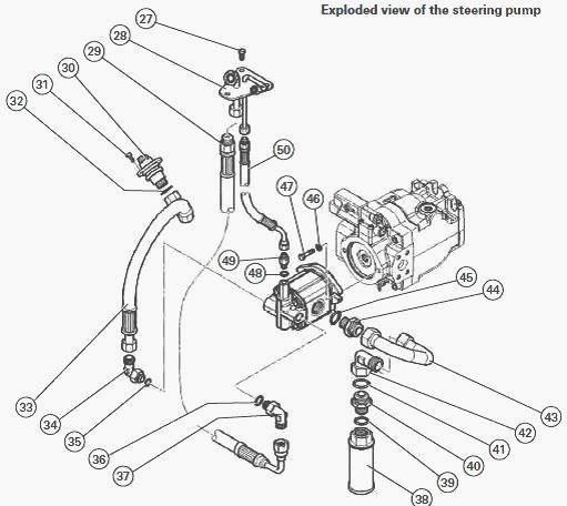
steering pump
27 – Screw, 28 - Union plate, 29 – Hose, 30 – Union, 31 – Screw, 32 -
O’ring, 33 – Hose, 34 – Union, 35 - O’ring, 36 - O’ring, 37 – Union, 38
– Strainer,39 – Seal,40
– Union,41 – Seal,42 – Union, 43 - Rigid pipe, 44 – Union, 45 - O’ring,
46 – Washer, 47 – Screw, 48 - O’ring, 49 – Union, 50 – Hose
Chock the MF 8730, 8737 tractor and take off the rear right-hand wheel.
Remove the exhaust system. Take off the right-hand protective guards.
Take off the
protective guard over the right-hand footstep. Remove the right-hand
footstep.
Drain and remove the fuel tank.
Drain the hydraulic oil. Remove the protective housings that might obstruct access. Disconnect the hydraulic pipes connected to the tank. Disconnect the hose (33) from the steering pump priority block. Take out the attachment screws (10) from the hydraulic pressure pipe of the variable displacement pump.
Take out the tank attachment screws.
Remove the oil tank. Take out the rigid pipe (9) through the port, then
disassemble it. Remove the hose (50) from the steering pump priority
block.
Take out the attachment screws (27) from the union plate (28).
Gently remove the plate from the spacer, and disassemble the hydraulic union from the priority block. Remove the “Load Sensing” control pipe from the variable displacement pump. Disconnect the hose (33) from the steering pump priority block. Loosen the collar (22), then disconnect the variable displacement pump suction hose (23).
Take off the rigid pipe (43) fitted with its strainer
(38). Access to the union is limited, so a 41 mm pipe wrench is
recommended. Remove the
union (44) from the pump. Take out the attachment screws (47) from the
steering pump. Remove the steering pump.
Discard the O’ring. Remove the coupling sleeve. Loosen and take out the
screws (3), then remove the pressure union of the variable displacement
pump. Access is limited, so a 10 mm multipurpose wrench is recommended.
Remove the return rigid pipe (13) to the variable displacement pump tank. Access is limited, so a 27 mm pipe wrench is recommended. Remove the screws (25) from the variable displacement pump flange. Access is limited, so an 18 mm offset pipe socket is recommended.
Support the variable displacement
pump across
the housing with a wooden shim, and pull the pump away of the gear
teeth. Take the pump out of the spacer;
Discard the paper gasket. It is recommended to turn the suction channel
of the pump upwards and to remove an attachment stud from the tank to
extract the pump
more easily.
Reassembling the steering pump and the variable displacement pump
Grease and fit new seals. Screw two M12 guide studs into M12 screw holes
to assist pump assembly. Insert the variable displacement pump into the
spacer and
slide it onto the studs. A wooden shim can be fitted to assist pump
positioning. Take out the guide studs and attach the pump using the two
M12 attachment screws
(25).
Tighten the M12 screws (25) to a torque of: 86Nm.
Fit the return rigid pipe (13) to the variable displacement pump tank.
Access is limited, so a 27 mm pipe wrench is recommended. Fit the
variable displacement
pump pressure hose (4). Tighten the screws (3) to a torque of: 50Nm. Fit
the coupling sleeve of the two pumps.
Fit a new O’ring on the steering pump centring diameter, and fit the steering pump in its housing. Fit and tighten the steering pump screws (47) to a torque of: 25Nm. Fit the steering pump union (44). Fit the steering pump rigid pipe (43) fitted with its strainer (38).
Connect the hose (23) on the variable
displacement pump suction
channel, and tighten the collar (22). Attach the hose (33) on the
steering pump priority block. Fit the elbow (17) on the variable
displacement pump. Fit the MF 8730,
8737 steering pump priority block hose (50) and tighten the three screws
(27) to a torque of: 10Nm.
Fit the hose (50) on the steering pump priority block. Take out the pressure hose (4) from the variable displacement pump through the spacer plug (6), and connect it to the rigid pipe (9) of the washer (8). Refit the stud if removed when extractng the pump. Clean the mating faces of the tank and spacer.
Smear one of the cleaned surfaces with sealing product. Fit the hydraulic tank. Fit and tighten the tank attachment screws. Tighten the screws (10) of the washer (8). Fit the hose to the union (30). Fit the tank hydraulic channels. Refit the protective housings that were removed. Refit the fuel tank. Refit the footstep.
Refit the
protective guard over the right-hand footstep. Refit the right-hand protective guards.
Refit the exhaust system. Top up the hydraulic oil (approximately 65L).
Check the operation and tightness of the hydraulic circuit. Repair any
defective elements or
seals. Refit the rear right-hand wheel.
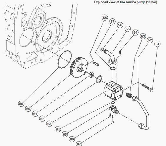
service pump (18 bar)
51 – Screw, 52 - Rigid pipe, 53 – Union, 54 – Screw, 55 – Union, 56 -
O’ring, 57 - O’ring, 58 – Screw, 59 - O’ring, 60 – Cover, 61 – Catchdog,
62 - O’ring, 63 -
Hydraulic pump, 64 - O’ring, 65 – Insert, 66 – Screw, 67 – Screw
Disassembling the lubricating pump
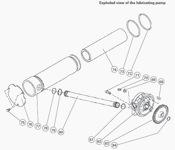
Lubricating pump
68 – Key, 69 – Washer, 70 – Screw, 71 – Screw, 72 - O’ring, 73 - O’ring,
74 – Filter, 75 – Screw, 76 – Cover, 77 - Suction filter, 78 - O’ring,
79 – Circlip, 80 – Pipe,
81 - O’ring, 82 – Pump, 83 - Drive pinion, 84 – Circlip
Remove the Massey Ferguson 8730, 8737 transmission unit. Take out the
screws (75), then remove the cover (76). Remove the filter (74). Loosen
the pipe on the
pressure filter side.
Loosen the pipe on the rear axle side. Remove the circlip (79) from the suction pipe. Fit home the suction pipe in the suction filter pipe to release it from the pump. Loosen and remove the 2 screws (71).
Remove the lubricating pump.
Remove the suction pipe. Discard the O’rings. Take off the pump pinion
circlip (84). Remove the pump pinion (83). Take off the key (68).
Check the pump condition, and replace it if required.
Reassembling the lubricating pump
Fit the key (68) in its housing. Fit the drive pinion (83). Fit the
shaft circlip (84). Fit the pump in its housing in the gearbox. Hold it
in position using 2 screws.
Refit the pipe on the pressure filter side and rear axle side. Prepare the suction pipe. Fit the 2 O’rings (81) and circlips (79).
Fit the side not fitted with the O’ring in the suction filter pipe (77). Smear the O'ring with miscible grease and fit home the pipe in the suction pump.
The circlip groove on
the suction filter pipe side must be cleared. Smear it with miscible
grease, then slide the
O’ring into its groove. Fit the circlip in its groove.
Fit the pipe into
the suction filter until it abuts against the circlip. Fit the circlip
on the pipe, on the pump side.
Definitively tighten the pump attachment screws to a torque of: 25 Nm.
Fit the suction filter (74). Fit the cover (76) using the 3 screws (75). Tighten the screws (75) to a torque of:25Nm. Refit the transmission unit.
________________________________________________________________________________
 SPECS
SPECS LOADERS
 MAINTENANCE
 PROBLEMS
________________________________________________________________________________________
 MF 1523
 MF 1531
 MF 135
 MF 1547
 MF 1635
________________________________________________________________________________________
 231
231 231S
231S 235
235 240
240 241
241________________________________________________________________________________________
 255
255 265
265 274
274 285
285 375
375________________________________________________________________________________________
________________________________________________________________________________________
 916X Loader
 921X Loader
 926X Loader
 931X Loader
 936X Loader
________________________________________________________________________________________
 941X Loader
 946X Loader
 951X Loader
 956X Loader
 988 Loader
________________________________________________________________________________________
 1655
1655 GS1705
 1742
1742 2635
2635 4608
4608________________________________________________________________________________________
 1080
1080 1100
1100 2615
2615 3050
3050 3060
3060________________________________________________________________________________________
 4708
4708 5455
5455 5450
5450 5610
5610 5613
5613________________________________________________________________________________________
 DL95 Loader
 DL100 Loader
 DL120 Loader
 DL125 Loader
 DL130 Loader
________________________________________________________________________________________
 DL135 Loader
 DL250 Loader
 DL260 Loader
 L90 Loader
 L100 Loader
________________________________________________________________________________________
 6499
6499 7480
7480 7618
7618 7726
7726 1533
1533________________________________________________________________________________________
 2604H
2604H 2607H
2607H 4455
4455 4610M
4610M 4710
4710________________________________________________________________________________________
 L105E Loader
 L210 Loader
 1014 Loader
 1016 Loader
 1462 Loader
________________________________________________________________________________________
 1525 Loader
 1530 Loader
 232 Loader
 838 Loader
 848 Loader
________________________________________________________________________________________
 5712SL
 6713
6713 6715S
6715S 7475
7475 7615
7615________________________________________________________________________________________
 7716
7716 7724
7724 8240
8240 8650
8650 8732
8732________________________________________________________________________________________
 246 Loader
 1036 Loader
 1038 Loader
 1080 Loader
 856 Loader