
________________________________________________________________________________
MTZ Belarus Tractor hydraulic power steering
Forward-Motion hydraulic power
steering
The hydraulic power steering is intended for controlling the turning of
the steerable wheels and reducing the force to be applied to the
steering wheel for turning the tractor.
The hydraulic power steering consists of a metering pump (1), two
differential hydraulic cylinders (3) executing the turn, feeding pump
(2) driven from the engine and hydraulic fittings.
The hydraulic power steering oil tank is the right-hand section of the
oil tank (4) with the 25-micron filter of the working fluid.
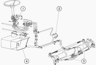
Fig.1. MTZ Belarus Tractor steering
1 – metering pump; 2 – feeding pump; 3 – hydraulic cylinders; 4 – oil
tank.
Construction and Operation of the
hydraulic power steering
The direct-acting metering pump (1) is installed on the bracket of the
steering column; the turn hydraulic cylinder (3) – on the brackets
attached to the front axle and the feed pump (2) – on the engine.
The metering pump is connected to the chambers of the hydraulic cylinder
of turning, feed pump and oil tank via pipe-lines.
When in a straight-ahead motion, the cylinder chambers are closed by the
metering pump spool belts, and the oil fed from the feed pump and
brought to the metering pump returns to the oil tank.
When the steering wheel is turned, the metering spool-valve is displaced
providing in such a way for oil supply to the chambers of the hydraulic
cylinder of turning in the amount proportional to the angle of turn of
the steering wheel.
Recommendations for Operation of the
hydraulic power steering
When assembling the MTZ Belarus Tractor
hydraulic power steering:
- Install properly the oil pipelines and hoses in accordance with the
hydraulic diagram;
- Protect the connecting holes of the metering pumps, hydraulic
cylinders, poi pipelines and high-pressure hoses against penetration of
dirt;
- Prior to starting the engine, check the tightening of all the
connections of the hydraulic power steering hydraulic system;
- When tightening the fasteners, apply the required torque;
- Fill the oil tank to the upper limit as seen on the level indicator;
Bleed air from the MTZ Belarus Tractor hydraulic system.
To do this, proceed as follows:
- Start the engine. Turn the steering wheel in both directions 3-4 times
at the idling rotational speed of the engine without reaching the
extreme positions of turning of the steerable wheels.
- Add oil to the tank to the required level.
- Turn the wheels from one stop to an-other 2-3 times. Hold the steering
wheel at the extreme positions for 4...5 seconds.
- If necessary, eliminate the oil leaks and add oil to the top level of
the tank.
- Drive the figure of eight to check the operation of the steering
control.
Metering Pump
The metering pump consists of assembly I, distributor II, non-return
valve (9), two anti-hammer valves (7), relief valve (6) and two
anti-vacuum valves (8).
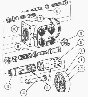
Fig.2. MTZ Belarus Tractor hydraulic steering
1 – stator; 2 – rotor; 3 – spool valve; 4 – power shaft; 5 – sleeve; 6 –
relief valve; 7 – anti-hammer valves; 8 – anti-vacuum valves; 9 –
non-return valve; 10 – body. I – pumping assembly; II – distributor
The Gerotor pumping assembly I consists of the stator (1) fixed on the
body and rotating rotor (2) connected to the spool valve (3) by the
power shaft (4).
The distributor II consists of the body (10),
sleeve (5) and spool valve (3) splined onto the tail-end of the power
shaft of the steering column:
- The relief valve (6) limits the maximum pressure in the pressure
mainline to within 17.5...18.0 MPa (175...180 kgf/cm2) in the hydraulic
power steering system with the double-rod hydraulic cylinder or to
within 14.0...14.5 MPa (140...145 kgf/cm2) in the hydraulic power
steering system with two hydraulic cylinders of steering control.
- The anti-hammer valves (7) limit pressure in the cylinder mainlines at
impact loads.
- The pressure setting of the anti-hammer valves is within 22.5...24.5
MPa (225...245 kgf/cm2).
- The anti-vacuum valves (8) make it possible to ensure the required
supply of the working fluid into the hydraulic cylinder in the emergency
mode and in case of operation of the anti-hammer valves.
________________________________________________________________________________
________________________________________________________________________________________
 SPECS
SPECS LOADERS
 MAINTENANCE
 PROBLEMS
________________________________________________________________________________________
 MF 1523
 MF 1531
 MF 135
 MF 1547
 MF 1635
________________________________________________________________________________________
________________________________________________________________________________________
 231
231 231S
231S 235
235 240
240 241
241________________________________________________________________________________________
 255
255 265
265 274
274 285
285 375
375________________________________________________________________________________________
________________________________________________________________________________________
 916X Loader
 921X Loader
 926X Loader
 931X Loader
 936X Loader
________________________________________________________________________________________
 941X Loader
 946X Loader
 951X Loader
 956X Loader
 988 Loader
________________________________________________________________________________________
 1655
1655 GS1705
 1742
1742 2635
2635 4608
4608________________________________________________________________________________________
 1080
1080 1100
1100 2615
2615 3050
3050 3060
3060________________________________________________________________________________________
 4708
4708 5455
5455 5450
5450 5610
5610 5613
5613________________________________________________________________________________________
 DL95 Loader
 DL100 Loader
 DL120 Loader
 DL125 Loader
 DL130 Loader
________________________________________________________________________________________
 DL135 Loader
 DL250 Loader
 DL260 Loader
 L90 Loader
 L100 Loader
________________________________________________________________________________________
 6499
6499 7480
7480 7618
7618 7726
7726 1533
1533________________________________________________________________________________________
 2604H
2604H 2607H
2607H 4455
4455 4610M
4610M 4710
4710________________________________________________________________________________________
 L105E Loader
 L210 Loader
 1014 Loader
 1016 Loader
 1462 Loader
________________________________________________________________________________________
 1525 Loader
 1530 Loader
 232 Loader
 838 Loader
 848 Loader
________________________________________________________________________________________
 5712SL
 6713
6713 6715S
6715S 7475
7475 7615
7615________________________________________________________________________________________
 7716
7716 7724
7724 8240
8240 8650
8650 8732
8732________________________________________________________________________________________
 246 Loader
 1036 Loader
 1038 Loader
 1080 Loader
 856 Loader