
________________________________________________________________________________
Disassembly and assembly the Orbitrol
If the Massey Ferguson 6465, 6490, 6495 Tractor Orbitrol steering unit
is defective, take care that it is replaced with a unit with exactly the
same characteristics.
OSPC 150 ON spool valve
OSP = Orbitrol steering pump
C = Valves incorporated in the steering unit
150 = 150 cm3 per rotor revolution
ON = Open centre without feedback
- Remove the spool valve from the Massey Ferguson 6465, 6490, 6495
Tractor and tighten it in a clamp with soft jaws.
- Remove the jaws if necessary. Take out the screws. Split the manifold
from the spool valve. Collect the seals.
- Take out the screws. Carefully mark the location of the screw and then
remove it.
- Remove the closing plate, O'ring, stator and O'ring. Remove the
spacer, the rotor, the distributor plate and the O'ring.
- Take out the splined link shaft. Unscrew the threaded ring and take
out the valve ball from the non-return valve.
- Take out the two pins and valve balls from the suction valves of the
MF 6465, 6490, 6495 steering unit.
- Extract the sleeve and spool valve assembly by pushing it out while
checking that the pin lies along the horizontal axis.
- Remove the washers, the needle bearing and the bush from the sleeve /
spool valve assembly. Remove the pin, and the centring springs by
pressing on their ends.
- Separate the sleeve from the spool valve.
- Unscrew the plug from the relief valve. Using an 8mm Allen wrench,
disassemble the threaded bush and remove the seal, the spring and the
valve (the crimped seat cannot be removed).
- Unscrew the two plugs from the shock valves. Remove seals. Using a 6mm
Allen wrench, remove the threaded bushes and take out the springs, the
valve balls and their seats (the crimped seats cannot be removed).
- Extract the seal, the bush and the O'ring. Disassemble the non-return
valve.
- Check and clean the components. Replace any defective parts. Lubricate
with clean transmission oil before reassembly.
- Reassemble the non-return valve. Install the seal, the O'ring and the
ring.
- Place the valve balls and springs in the recesses of the shock valves.
Screw on the threaded bushes. Fit the seals and tighten the plugs.
- Install the valve and spring in the recesses of the relief valve.
Screw in the threaded bush. Fit the seal and tighten the plug to a
torque of 40-60 Nm.
- Insert the spool valve into the sleeve. Position the centring springs
and insert the pin.
- Position the bush on the sleeve and spool valve assembly so that the
chamfer facilitates assembly in the steering unit.
- Place the washers, the chamfer of washer towards the centring springs,
by inserting the needle bearing between them.
- Install the Massey Ferguson 6490, 6495, 6465 Tractor sleeve and spool
valve assembly in the steering unit by oscillating it slightly. Check
that the pin is held horizontally.
- Place the two valve balls and the two pins in the recesses of the
suction valves.
- Install the valve ball in the non-return valve recess. Screw in the
threaded bush.
- Position the splined link shaft. Install the O'ring and the
distributor plate.
- Install the rotor so that the two concave depressions lie along the
axis of the slot in the splined link shaft. Install the spacer. Place
the O'rings on the stator.
- While avoiding moving the rotor, fit the stator. Then move it so that
its fixing holes match with those of the steering unit. Install the
closing plate.
Replace the seals and fit:
- the screw (in the positions marked during disassembly);
- the opposing screws tightened to 30-35 Nm;
- the manifold on the steering unit (screws tightened to 60 Nm);
- the sleeves on the manifold.
Using a test-bench or a suitable fixture, check the adjustment and
correct operation of the steering unit. Install the steering unit on the
tractor.
Removing and install the MF 6490,
6465, 6495 Tractor steering Ram
- The general procedure is similar on fixed or suspended front axles.
- Immobilise the tractor. Chock the rear wheels. Apply the handbrake.
- To help release the steering ram from its overlap flange, first remove
the front left-hand wheel and mudguard (if fitted).
- Remove the locknuts and drive ou the steering pivot balls using a
suitable extractor tool.
- Loosen nut. Remove the right-hand steering link rod (including pivot
ball).
- Disconnect and block the supply hoses (right and left) from the ram,
marking their positioning.
- Take out the screws and remove the ram. Install the steering ram.
Tighten the screws to a torque of 120 Nm.
- Reconnect the left-hand and right-hand supply hoses of the ram.
Install the link rod and steering pivot balls.
- Reassemble the wheel(s). Tighten the nuts and screws to their
indicated torque, depending on version. Adjust wheel alignment.
Complete the operation by tightening:
- steering pivot ball nuts to a torque of 220 Nm;
- steering link rod nuts.
Disassembling and reassembling
operations
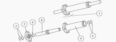
Fig.25,26. The Massey Ferguson MF 6465, 6490, 6495 Tractor
steering ram assembly (1) comprises the following parts
(2) Pack of seals (4) Cylinder (6) Piston pin (7) Cover

- Release and remove the ball joints (7).
- Separate the cover (7) from the cylinder (4).
- Take out the piston (6) from cylinder.
- Discard all the seals (sealing ring, O'rings and dust seal).
- Ensure that the internal bore of the cylinder and the operational
parts of the piston rod are free of scratches: scratches can cause leaks
in the steering unit.
- Lubricate the seals, bushes and cylinder internal bore with clean
transmission oil.
- Install the seals on the piston rod (6) cylinder (4) and the cover (7)
respectively.
Put together the MF 6465, 6490, 6495 Tractor
steering ram without damaging the oil tight seals:
- slide the piston rod fitted with its seals in the cylinder bore;
- put the cover back on the cylinder, with the pressure inlet facing the
right direction.
- Tighten and lock the ball joints (7) to the torque of 300 Nm. Install
the steering ram on the tractor.
- Check the hydraulic pressure on the cylinder line. Carry out a road
test on the steering system.
________________________________________________________________________________
________________________________________________________________________________________
 SPECS
SPECS LOADERS
 MAINTENANCE
 PROBLEMS
________________________________________________________________________________________
 MF 1523
 MF 1531
 MF 135
 MF 1547
 MF 1635
________________________________________________________________________________________
________________________________________________________________________________________
 231
231 231S
231S 235
235 240
240 241
241________________________________________________________________________________________
 255
255 265
265 274
274 285
285 375
375________________________________________________________________________________________
________________________________________________________________________________________
 916X Loader
 921X Loader
 926X Loader
 931X Loader
 936X Loader
________________________________________________________________________________________
 941X Loader
 946X Loader
 951X Loader
 956X Loader
 988 Loader
________________________________________________________________________________________
 1655
1655 GS1705
 1742
1742 2635
2635 4608
4608________________________________________________________________________________________
 1080
1080 1100
1100 2615
2615 3050
3050 3060
3060________________________________________________________________________________________
 4708
4708 5455
5455 5450
5450 5610
5610 5613
5613________________________________________________________________________________________
 DL95 Loader
 DL100 Loader
 DL120 Loader
 DL125 Loader
 DL130 Loader
________________________________________________________________________________________
 DL135 Loader
 DL250 Loader
 DL260 Loader
 L90 Loader
 L100 Loader
________________________________________________________________________________________
 6499
6499 7480
7480 7618
7618 7726
7726 1533
1533________________________________________________________________________________________
 2604H
2604H 2607H
2607H 4455
4455 4610M
4610M 4710
4710________________________________________________________________________________________
 L105E Loader
 L210 Loader
 1014 Loader
 1016 Loader
 1462 Loader
________________________________________________________________________________________
 1525 Loader
 1530 Loader
 232 Loader
 838 Loader
 848 Loader
________________________________________________________________________________________
 5712SL
 6713
6713 6715S
6715S 7475
7475 7615
7615________________________________________________________________________________________
 7716
7716 7724
7724 8240
8240 8650
8650 8732
8732________________________________________________________________________________________
 246 Loader
 1036 Loader
 1038 Loader
 1080 Loader
 856 Loader