
________________________________________________________________________________
Massey Ferguson 6475 Tractor steering ram
Removing and install the 2 WD steering
ram
Immobilise the Massey Ferguson 6475, 6470, 6455 Tractor. Chock the rear
wheels. Apply the handbrake.
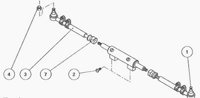
Fig.43
If necessary, remove the front wheel(s). Place one or more safety
stand(s).
Disconnect and block off the left- and right-hand ram supply hoses,
carefully identifying their positions.
Drive out the ball joints (1) from the steering arms using a suitable
extractor. Loosen the screws (2).
Remove the ram with its link rods (3) and ball joints (7). If necessary,
split the link rods and O’rings from the ram.
If removed, assemble onto the ram:
- the ball joints (7);
- the link rods (3).
Install the complete ram.
Lightly smear the thread of the screws (2) with Loctite 270 or
equivalent. Fit and tighten these screws, with their washers, to a
torque of 120 Nm.
Attach the steering ball joints (1). Fit and tighten their locknut (4)
to a torque of 115 - 130 Nm.
Reconnect the left- and right-hand ram supply hoses, in their initial
positions.
If removed, refit the wheel(s). Remove the safety stand(s). Tighten the
wheel studs to a torque of 200 - 260 Nm.
Remove the chocks from the rear wheels. Carry out a road test on the MF
6475, 6470, 6455 Tractor steering system. Check the oil tightness of the
hydraulic unions.
Removing - install and disassembling -
assembling the CARRARO 4 WD steering ram
Immobilise the tractor. Chock the rear wheels. Apply the handbrake.
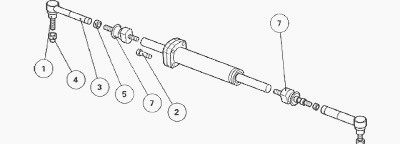
Fig.44
Take off the front left-hand mudguard and wheel.
Disconnect and block off the left and right-hand ram supply hoses,
carefully identifying their positions.
Drive out the ball joints (1) from the steering arms using a suitable
extractor. Loosen the screws (2).
Remove the ram with its link rods (3) and ball joints (7). If necessary,
split the link rods and O’rings from the steering ram.
If removed, assemble onto the ram:
- the ball joints (7);
- the link rods (3).
Install the complete Massey Ferguson 6470, 6475, 6455 Tractor steering
ram.
Lightly smear the thread of the screws (2) with Loctite 270 or
equivalent. Insert and tighten these screws, with their washers, to a
torque of 120 Nm.
Fix the steering ball joints (1). Insert and tighten their locknut (4)
to a torque of 220 Nm.
Reconnect the left and right-hand ram supply hoses, in their initial
positions.
If removed, refit the mudguard and wheel. Remove the safety stand.
Tighten the wheel nuts to a torque of 640 - 680 Nm.
Disassembly steering ram
Remove the steering ram (see previous operations).
Loosen and remove the ball joints (7) using a suitable wrench.
Separate the cover (7) from the cylinder (4).
Take out the piston/rod (6) from cylinder.
Systematically discard all the sealing rings, seals and dust guards.
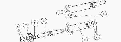
Fig.45. Parts list
(1) Ram assembly (2) Pack of seals (4) Cylinder (6) Rod/piston (7) Cover
Reassembly MF 6475, 6470, 6455 Tractor
steering ram
Clean the components. Replace any defective parts.
Check the surface condition:
- of the inner cylinder bore;
- of the rod/piston functional parts.
Systematically discard scratched parts that may lead to steering ram
leaks.
Lubricate with clean transmission oil:
- the new rings and joints;
- the inner cylinder bore;
- the rod/piston.
Carefully fit the joints on:
- the rod/piston (6);
- the cylinder (4);
- the cover (7).
Reassemble the Massey Ferguson 6475, 6470, 6455 Tractor steering ram
without damaging the oil tight seals.
For this purpose:
- slide the rod/piston, with its seals, into the cylinder;
- put the cover back on the cylinder, with the pressure inlet facing the
right direction.
Screw on the ball joints (7). Tighten to a torque of 300 Nm. Install the
steering ram.
If necessary, check the pressure at the ram hydraulic ports.
Carry out a road test on the steering system. Check the oil tightness of
the ram and hydraulic unions.
Removing - refitting and disassembling
- reassembling the DANA 4 WD steering ram
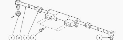
Fig.46
Immobilise the tractor. Chock the rear wheels. Apply the handbrake.
If access to steering ram fixing screws (2)
seems difficult:
- raise the front of the tractor with a trolley jack placed in the
centre of the front axle;
- remove the front wheels;
- place a suitable axle stand beneath the lower engine housing;
- swing the front axle at maximum to high and low positions in order to
access the screws.
Disconnect and block off the steering ram feed hoses, carefully
identifying their positions.
Drive out the ball joints (1) from the steering arms using a suitable
extractor.
Loosen the screws (2). Remove the steering ram.
Install the steering ram.
Lightly smear the thread of the screws (2) with Loctite 270 or
equivalent. Tighten these screws to a torque of 180 - 200 Nm.
Fix the steering ball joints (1). Tighten their locknut (4) to a torque
of 115 - 130 Nm. Lock the nuts (4) using new pins.
Reconnect the steering ram supply hoses, in their initial positions.
If removed, refit the wheels. Tighten the wheel nuts to a torque of 400
- 450 Nm.
Disassembly MF 6470, 6475, 6455
Tractor steering ram
DANA front axles are fitted with a double acting steering ram. It
receives pressure from the steering unit as a function of the rotation
of the steering wheel. When one side of the ram is fed, the other is
connected to the return pipes and vice versa.
Each component can be replaced and is listed in the spare parts
catalogue. A pack provides all the seals necessary for carrying out
service operations.
Remove the steering ram. Release and remove the ball joints (7).
Take off the lock rings (5) using a suitable locally made tool, while
simultaneously turning the guide rings (3).
Take out the piston rod (6) from cylinder (4).
Discard all the seals (sealing ring, O'rings, dust guards and lock
rings).
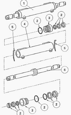
Fig.47. Parts list
(1) Ram assembly (2) Pack of seals (3) Guide rings (4) Cylinder (5) Lock
rings (6) Rod/piston
Assembly Massey Ferguson MF 6475,
6470, 6455 Tractor steering ram
Clean the components. Replace any defective parts.
Check the surface condition:
- of the inner cylinder bore;
- of the rod/piston functional parts.
Systematically discard scratched parts that may lead to steering ram
leaks.
Lubricate with clean transmission oil:
- the O'rings;
- the rings;
- the inner cylinder bore.
Install the concerned seals on:
- the rod/piston (6);
- the guide rings (3).
Slide the piston rod fitted with its seals in the cylinder bore.
Install the guide rings at each end of the cylinder, taking care not to
damage the lip of the sealing rings.
Position the machined groove of each guide ring opposite the cylinder
groove. Turn the guide rings while simultaneously slipping in the lock
rings.
Tighten and lock the ball joints (7) to a torque of 120 - 150 Nm, the
threads previously smeared with Loctite 270 or equivalent.
Install the steering ram on the tractor.
Check the ram supply and tightness.
Carry out a road test on the steering system.
________________________________________________________________________________
________________________________________________________________________________________
 SPECS
SPECS LOADERS
 MAINTENANCE
 PROBLEMS
________________________________________________________________________________________
 MF 1523
 MF 1531
 MF 135
 MF 1547
 MF 1635
________________________________________________________________________________________
________________________________________________________________________________________
 231
231 231S
231S 235
235 240
240 241
241________________________________________________________________________________________
 255
255 265
265 274
274 285
285 375
375________________________________________________________________________________________
________________________________________________________________________________________
 916X Loader
 921X Loader
 926X Loader
 931X Loader
 936X Loader
________________________________________________________________________________________
 941X Loader
 946X Loader
 951X Loader
 956X Loader
 988 Loader
________________________________________________________________________________________
 1655
1655 GS1705
 1742
1742 2635
2635 4608
4608________________________________________________________________________________________
 1080
1080 1100
1100 2615
2615 3050
3050 3060
3060________________________________________________________________________________________
 4708
4708 5455
5455 5450
5450 5610
5610 5613
5613________________________________________________________________________________________
 DL95 Loader
 DL100 Loader
 DL120 Loader
 DL125 Loader
 DL130 Loader
________________________________________________________________________________________
 DL135 Loader
 DL250 Loader
 DL260 Loader
 L90 Loader
 L100 Loader
________________________________________________________________________________________
 6499
6499 7480
7480 7618
7618 7726
7726 1533
1533________________________________________________________________________________________
 2604H
2604H 2607H
2607H 4455
4455 4610M
4610M 4710
4710________________________________________________________________________________________
 L105E Loader
 L210 Loader
 1014 Loader
 1016 Loader
 1462 Loader
________________________________________________________________________________________
 1525 Loader
 1530 Loader
 232 Loader
 838 Loader
 848 Loader
________________________________________________________________________________________
 5712SL
 6713
6713 6715S
6715S 7475
7475 7615
7615________________________________________________________________________________________
 7716
7716 7724
7724 8240
8240 8650
8650 8732
8732________________________________________________________________________________________
 246 Loader
 1036 Loader
 1038 Loader
 1080 Loader
 856 Loader