________________________________________________________________________________
Massey Ferguson 8480, 8460 Tractor Steering System
The steering system used on Massey Ferguson 8480, 8460, 8470, 8450
Tractors fitted with a DYNA VT transmission and closed centre hydraulics
is dynamic, and there is no mechanical link between the steering wheel
and the steering ram. Its control principle is of the "Load Sensing"
type.
The system comprises the following main
components:
- a pressurised oil supply, from a fixed displacement pump via a
priority valve,
- an Orbitrol steering unit: OSPDF 80/240 LS Dynamic 4WD with closed
centre, by-pass mounted on tractors fitted with a 4WD Dana AG210 or
AG280 front axle.
- a double acting steering ram fitted to the 4WD front axle.
The Orbitrol is supplied by a fixed flow rate pump via a priority block.
The priority block is controlled by the steering unit Load Sensing line,
and directs priority oil flow to the steering circuit; excess flow is
redirected to the distribution block then to the cooling circuit.
When MF 8480, 8460, 8470, 8450 Tractor steering remains in neutral, all
pump flow is directed to the cooling system. When the steering wheel is
turned, the necessary flow of oil is directed to the corresponding side
of the steering ram. The other side of the ram is connected to the tank
return ports.
In case of engine breakdown or fixed displacement pump failure, the
Orbitrol acts as a hand-operated pump so that the steering can be
controlled. This obviously requires a much greater effort to be applied
to the steering wheel.
The Orbitrol OSPDF 80/240 comprises twin stator rotors of different
capacities.
Specifications:
- Shock valves setting: 225 -245 bar
- Supply valve setting: 155 -160 bar
- Steering unit capacity: 240 cm3 / turn
- Steering unit capacity: 80 cm3 / turn
- Supply valve setting: 10 bar
- Return to neutral springs torque: 1.5 daNm
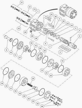
Disassembly and assembly the Orbitrol
steering 80/240cm3

Fig.41. Parts list
(1) Lip seal (2) Centring springs (3) Bush (4) O’ring (5) Cotter pin (6)
Sleeve (7) Spool valve (8) O’ring (9) Link shaft (10) O’ring (11) Plate
(12) O’ring (13) Plate (14) O’ring (15) Spacer (16) O’ring (17) O’ring
(18) Integrated spool (19) Spool body (20) Seals (21) O’ring (22) Washer
(23) Needle bearing (24) Washer (25) Relief valve (26) Orbitrol steering
unit (27) Rotor (gear type 80 cm3) (28) Stator (gear type 80 cm3) (29)
O’ring (30) Stator (gear type 205 cm3 or 240 cm3) (31) Rotor (gear type
205 cm3 or 240 cm3) (32) Plate (33) Spring (34) O’ring (35) Closing
plate (36) Screw (37) Shock valves (38) Non-return valve (39) Spacers
(40) Non-return valve (41) Suction valve (42) Cotter pin
- Remove the steering unit from the tractor.
- Place the Massey Ferguson 8460, 8470, 8480, 8450 Tractor steering unit
in a vice fitted with plastic jaws.
- Mark the location of the screws (36) and remove them. Remove seals
(20).
- Take off the closing plate (35), the O'ring (34), the body (19), the
integrated spool (18) and spring (33).
- Remove the O'ring (17). Locate the position of plate (32) and remove
it.
- Remove the O'ring (16). Remove stator (30) and rotor (31). Remove the
O'ring (14). Locate the position of plate (13) and remove it.
- Remove spacer (15), stator (28), rotor (27). Locate the position of
plate (11) and remove it. Remove the O'ring (10).
- Take out the splined link shaft (9).
- Unscrew the threaded bush and recover the ball from the non-return
valve (38).
- Take out the two axle pins and the balls from the suction valves (41)
of the steering unit.
- Extract the sleeve (6) and spool valve (7) assembly by pushing it out
while checking that the pin (5) lies along the horizontal axis.
- Remove the washers (22) (24), the needle bearing (23) and the bush (3)
from the sleeve and spool valve assembly. Remove the pin (5), and the
centring springs (2) by pressing on their ends. Separate the sleeve (6)
from the spool valve (7).
- Unscrew the plug from the relief valve (25). Using an 8 mm Allen
wrench, disassemble the threaded bush and remove the seal, the spring
and the valve (the crimped seat cannot be removed).
- Unscrew the two plugs from the shock valves (37) and remove the seals.
Using a 6 mm Allen wrench, remove the threaded bushes and take out the
springs, the valve balls and their seats (the crimped seats cannot be
removed).
- Extract the seal (1) and O'ring (21). Disassemble the non-return valve
(40).
- Check and clean all components. Replace any defective parts. Lubricate
the components with clean transmission oil.
- Reassemble the non-return valve (40). Install the seal (1) and O'ring
(21).
- Place the valve balls and springs in the recesses of the shock valve
(37). Screw in the threaded bushes, fit the seals and tighten the plugs.
- Install the valve and spring in the recesses of the relief-valve (25),
screw in the threaded bush. Fit the seal and tighten the plug to a
torque of 40 - 60 Nm.
- Insert the spool valve (6) into the sleeve (7). Position the centring
springs (2) and insert the pin (5).
- Position the bush (3) on the sleeve and spool valve assembly so that
the chamfer facilitates assembly in the steering unit.
- Place the washers (22) (24), the chamfer of washer (24) towards the
centring springs (2), by inserting the needle bearing (23) between them.
- Install the sleeve and spool valve assembly in the MF 8480, 8460,
8470, 8450 Tractor steering unit by oscillating it slightly. Check that
the pin (5) is held horizontally.
- Install the two valve balls and the two pins in the recesses of the
suction valves (41).
- Install the valve ball in the recess of the non-return valve (38) and
screw in the threaded bush.
- Position the splined link shaft (9). Install the O'ring (10) and the
distributor plate (11).
- Install the rotor (27) so that the two concave depressions C lie along
the axis of the slot in the splined link shaft (9).
- Place the O'rings (12)(29) on the stator (28).
- Align the stator (28) fitting holes with those of the spool valve.
Refit the stator on the spool valve without moving the rotor (27). The
rotor (27) and the pin (5) must be in the correct position.
- Install rotor (31) on the spacer (15) so that the two depressions C
lie in the axis of the slot of splined shaft (9).
- Place the O'rings (14)(16) on the stator (30). Fit and move the stator
(30) with an angular movement so that the fixing holes align with those
provided in the steering unit.
- Install plate (32) in the position marked at disassembly.
- Check that there are no scratches on the bore of the body (19) or on
the spool rim (18).
- Check that the spool moves normally in the body.
- Slide the spool fitted with its oil tightness components into the
body. Fit O'rings (17) (34) and spring (33). Install the cover plate
(35).
- Install the new seals (20) and screws (36) as marked at disassembly.
Alternately tighten the screws to a torque of 30 - 35 Nm.
- Using a test-bench or a suitable fixture, check the adjustment and
correct operation of the steering unit.
- Install the steering unit on the Massey Ferguson 8480, 8460, 8470,
8450 Tractor. Check the oil tightness of the hydraulic unions.
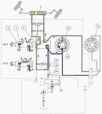
Manual steering (engine stopped)
When the pump is no longer providing pressure or when the pressure is
too low, the rotors (27) (31) are no longer hydraulically driven. It is
no longer power assisted. In this case, action on the steering wheel
compresses the centring springs (2).
The angular clearance between pin (5) and sleeve (6) is caught up and
there is a mechanical driving of the metering device (stator (28) and
rotor (27) only). The steering unit then operates in the same way as a
hand pump.
The oil returning from MF 8460, 8480, 8470, 8450 Tractor steering ram A
passes through the non-return valve (38) and supplies the metering
device. The pressure generated is proportional to the torque applied to
the steering wheel. A great effort is therefore required to turn the
wheel in order to steer the tractor.

Fig.42. Legend
A - Double acting steering ram, BP - Priority block(s), L - LH hydraulic
port of the steering ram, LS - Signal, P - Pressure, R - RH hydraulic
port of the steering ram, T - Return.
________________________________________________________________________________
________________________________________________________________________________________
________________________________________________________________________________________
________________________________________________________________________________________
________________________________________________________________________________________
________________________________________________________________________________________
________________________________________________________________________________________
________________________________________________________________________________________
________________________________________________________________________________________
________________________________________________________________________________________
________________________________________________________________________________________
________________________________________________________________________________________
________________________________________________________________________________________
________________________________________________________________________________________
________________________________________________________________________________________
________________________________________________________________________________________
________________________________________________________________________________________
________________________________________________________________________________________
________________________________________________________________________________________
 SPECS
SPECS LOADERS
 MAINTENANCE
 PROBLEMS
 MF 1523
 MF 1531
 MF 135
 MF 1547
 MF 1635
 231
231 231S
231S 235
235 240
240 241
241 255
255 265
265 274
274 285
285 375
375 916X Loader
 921X Loader
 926X Loader
 931X Loader
 936X Loader
 941X Loader
 946X Loader
 951X Loader
 956X Loader
 988 Loader
 1655
1655 GS1705
 1742
1742 2635
2635 4608
4608 1080
1080 1100
1100 2615
2615 3050
3050 3060
3060 4708
4708 5455
5455 5450
5450 5610
5610 5613
5613 DL95 Loader
 DL100 Loader
 DL120 Loader
 DL125 Loader
 DL130 Loader
 DL135 Loader
 DL250 Loader
 DL260 Loader
 L90 Loader
 L100 Loader
 6499
6499 7480
7480 7618
7618 7726
7726 1533
1533 2604H
2604H 2607H
2607H 4455
4455 4610M
4610M 4710
4710 L105E Loader
 L210 Loader
 1014 Loader
 1016 Loader
 1462 Loader
 1525 Loader
 1530 Loader
 232 Loader
 838 Loader
 848 Loader
 5712SL
 6713
6713 6715S
6715S 7475
7475 7615
7615 7716
7716 7724
7724 8240
8240 8650
8650 8732
8732 246 Loader
 1036 Loader
 1038 Loader
 1080 Loader
 856 Loader