
________________________________________________________________________________
Disassembly and assembly the Orbitrol steering unit 160/125 cm3
- Remove the steering unit from the Massey Ferguson 6460, 6499, 6497
Tractor.
- Place the steering unit in a vice fitted with plastic jaws.
- Take out the screws (1). Carefully mark the location of the screw (2)
and then remove it.
- Remove the cover plate (4), O'ring (5), stator (6) and O'ring (8).
- Remove the spacer (10), the rotor (9), the distributor plate (29) and
the O'ring (28).
- Take out the splined link shaft (11).
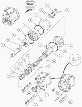
Fig.33. Parts list
(23) Suction valves (24) Bush (25) Spool valve (26) Non-return valve
(27) Sleeve (28) O’ring (29) Distributor plate (1) Screw (2) Screw (3)
Seal (4) Closing plate (5) O’ring (6) Stator (7) Cotter pin (8) O’ring
(9) Rotor (10) Spacer (11) Link shaft (12) Washer (13) Centring springs
(14) Needle bearing (15) Bush (16) Washer (17) O’ring (18) Relief valve
(19) Seal (20) Shock valve (21) Orbitrol steering unit (22) Non-return
valve
- Unscrew the threaded bush and recover the ball from the non-return
valve (22).
- Take out the two axle pins and the balls from the suction valves (23)
of the Massey Ferguson 6460, 6499, 6497 Tractors steering unit.
- Extract the sleeve (27) and spool valve (25) assembly by pushing it
out while checking that the pin (7) lies along the horizontal axis.
- Remove the washers (12) (16), the needle bearing (14) and the bush
(24) from the sleeve and spool valve assembly. Remove the pin (7), and
the centring springs (13) by pressing on their ends. Separate the sleeve
(27) from the spool valve (25).
- Unscrew the plug from the relief valve (18). Using an 8 mm Allen
wrench, disassemble the threaded bush and remove the seal, the spring
and the valve (the crimped seat cannot be removed).
- Unscrew the two plugs from the shock valves (20) and remove the seals.
Using a 6 mm Allen wrench, remove the threaded bushes and take out the
springs and valve balls from their seats (the crimped seats cannot be
removed).
- Extract the seal (19), the bush (15) and the O'ring (17).
- Disassemble the non-return valve (26).
- Check and clean all components. Replace any defective parts. Lubricate
the components with clean transmission oil.
- Reassemble the non-return valve (26).
- Install the seal (19), the O'ring (17) and the ring (15).
- Place the valve balls and springs in the recesses of the shock valve
(20). Screw in the threaded bushes, fit the seals and tighten the plugs.
- Install the valve and spring in the recesses of the relief-valve (18),
screw in the threaded bush. Fit the seal and tighten the plug to a
torque of 40 - 60 Nm.
- Insert the MF 6460, 6499, 6497 Tractor spool valve (25) into the
sleeve (27). Position the centring springs (13) and insert the pin (7).
- Position the bush (24) on the sleeve and spool valve assembly so that
the chamfer facilitates assembly in the steering unit.
- Place the washers (12) (16), the chamfer of washer (12) towards the
centring springs (13), by inserting the needle bearing (14) between
them.
- Install the sleeve and spool valve assembly in the steering unit by
oscillating it slightly. Check that the pin (7) is held horizontally.
- Install the two valve balls and the two pins in the recesses of the
suction valves (23).
- Install the valve ball in the recess of the non-return valve (22) and
screw in the threaded bush. Position the splined link shaft (11).
- Install the O'ring (28) and the distributor plate (29).
- Install the rotor (9) so that the two concave depressions C lie along
the axis of the slot in the splined link shaft (11). Refit the spacer
(10).
- Place the O'rings (5 )(8) on the stator (6).
- Align the stator (6) fitting holes with those of the Massey Ferguson
MF 6499, 6497, 6460 Tractor steering unit. Refit the stator on the
steering unit without moving the rotor (9). Install the cover plate (4).
- Install the screw (2) (in the same location as marked during
disassembly) and the screws (1) fitted with their seals (3). Tighten
opposing screws to a torque of 30 - 35 Nm.
- Using a test-bench or a suitable fixture, check the adjustment and
correct operation of the steering unit.
- Install the steering unit on the tractor. Check the oil tightness of
the hydraulic unions.
Manual steering (engine stopped)
When the pump is no longer operating or the available pressure is too
low the rotor is no longer hydraulically driven. It is no longer power
assisted. In this case, action on the steering wheel compresses the
centring springs.
The angular clearance between the pin and the sleeve is reduced to zero
resulting in mechanical rotation of stator and rotor.
The MF 6460, 6499, 6497 Tractor steering unit then operates in the same
way as a hand pump. The oil arriving from steering ram passes through
the non-return valve and supplies the metering device.
The pressure generated is proportional to the torque applied to the
steering wheel. A great effort is therefore required to turn the wheel
in order to steer the tractor.
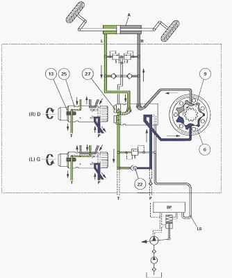
Fig.34. Legend
A - Double acting steering ram, BP - Priority block(s), L - LH hydraulic
port of the steering ram, LS - Signal, P - Pressure, R - RH hydraulic
port of the steering ram, T - Return.
________________________________________________________________________________
________________________________________________________________________________________
 SPECS
SPECS LOADERS
 MAINTENANCE
 PROBLEMS
________________________________________________________________________________________
 MF 1523
 MF 1531
 MF 135
 MF 1547
 MF 1635
________________________________________________________________________________________
________________________________________________________________________________________
 231
231 231S
231S 235
235 240
240 241
241________________________________________________________________________________________
 255
255 265
265 274
274 285
285 375
375________________________________________________________________________________________
________________________________________________________________________________________
 916X Loader
 921X Loader
 926X Loader
 931X Loader
 936X Loader
________________________________________________________________________________________
 941X Loader
 946X Loader
 951X Loader
 956X Loader
 988 Loader
________________________________________________________________________________________
 1655
1655 GS1705
 1742
1742 2635
2635 4608
4608________________________________________________________________________________________
 1080
1080 1100
1100 2615
2615 3050
3050 3060
3060________________________________________________________________________________________
 4708
4708 5455
5455 5450
5450 5610
5610 5613
5613________________________________________________________________________________________
 DL95 Loader
 DL100 Loader
 DL120 Loader
 DL125 Loader
 DL130 Loader
________________________________________________________________________________________
 DL135 Loader
 DL250 Loader
 DL260 Loader
 L90 Loader
 L100 Loader
________________________________________________________________________________________
 6499
6499 7480
7480 7618
7618 7726
7726 1533
1533________________________________________________________________________________________
 2604H
2604H 2607H
2607H 4455
4455 4610M
4610M 4710
4710________________________________________________________________________________________
 L105E Loader
 L210 Loader
 1014 Loader
 1016 Loader
 1462 Loader
________________________________________________________________________________________
 1525 Loader
 1530 Loader
 232 Loader
 838 Loader
 848 Loader
________________________________________________________________________________________
 5712SL
 6713
6713 6715S
6715S 7475
7475 7615
7615________________________________________________________________________________________
 7716
7716 7724
7724 8240
8240 8650
8650 8732
8732________________________________________________________________________________________
 246 Loader
 1036 Loader
 1038 Loader
 1080 Loader
 856 Loader