________________________________________________________________________________
AG150/AG250 transmission Overhaul - Reassembling the Massey Ferguson 8220 tractor clutch
Reassembling the Massey Ferguson 8250, 8240, 8220 tractor speed clutch
train
Place the clutch train vertically on the bench. Refit the internal and
external seals on piston. Smear the piston seals and clutch-housing bore
with transmission oil.
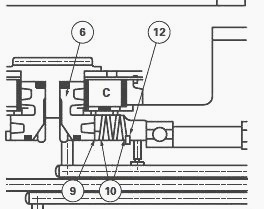
Fit the piston with the pockets and grooves on the outside. Install an
oil seal washer (9). All the clutch oil seal washers are identical.
Reassemble the Belleville washers
(10).
The diameter of the first Belleville washer must be in contact with the
oil seal washer. The second Belleville washer must be in contact with
the external diameter of the
first washer. Alternate the Belleville washers until they are all
installed.

Fig.56. Reassembling the MF 8220, 8240, 8250 tractor speed clutch train
(6) Piston (9) Washer - oil stop (10) Belleville washers (12) Circlip
holding washer and circlip.
Place the clutch train on a press. Using tool ATP 3002 compress the
Belleville washers and fit a holding washer and a circlip.
Before assembly, lubricate the thrust plates and discs with transmission
oil. Alternate 10 thrust plates with 10 discs, beginning with a thrust
plate on the piston. Fit the
closing plate and circlip.
Measuring piston travel
- Using a depth gauge, measure distance (A) from the end of the piston
to the edge of the clutch housing.
- Inject compressed air at 4.8 bars into the piston supply channel to
compress the Belleville washers.
- Measure distance (B) from the end of the piston to the edge of the
clutch housing.
- The difference between these two measurements, A - B, equals the
piston travel.
Piston travel
- The piston travel can be adjusted by selecting or exchanging
intermediate plates since their thickness
varies.
- With new thrust plates and discs: Piston travel - 1.3 - 3.8 mm
- With used thrust plates and discs: Piston travel - 1.8 - 5.5 mm
Reassembling Massey Ferguson 8220, 8240, 8250 tractor clutch bearings
Certain bearings used in the clutches and shafts require installing in
the correct direction.
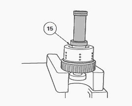
- Reassemble bearing (15) the nearest to the clutch linings, using the
ATP 3020 sleeve.

Fig.57
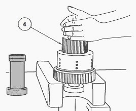
- Reassemble the pinion with the clutch hub (4) in the discs or thrust
plates and above the bearing (15). The pinion is slid over the bearing.
Turn and lightly shake the
pinion until all the splines of the discs and thrust plates are engaged
and bearing (15) is at the bottom of the bore of the pinion.

Fig.58
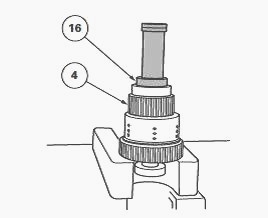
- Reassemble the external pinion hub bearing (16) on the shaft and push
it into the pinion hub. Fit the circlip on the shaft.
- Place the extractor on the pinion (4), pull the pinion and bearing
(16) against circlip to eliminate any lateral load being placed on the
bearings.

Fig.59
The pinion hub must move longitudinally.
- Install the shaft bearing on the shaft and push it into its
emplacement.
- Repeat the procedure for each end of the shaft and for all the other
speed clutch shafts.

Fig.60. Input shaft - 1st stage shaft (John Deere AG 150 transmission of MF 8220, 8240, 8250 tractor)
(1) 1st stage shaft - 32 teeth (2) At the rear - roller bearing (3) At
the front - ball bearing.
Instructions
(2) Install the roller bearing with the bearing circlip facing the
pinion.
John Deere AG 250 transmission of Massey Ferguson MF 8250, 8240, 8220
tractor (Fig.60)
(1) 1st stage shaft - 38 teeth (2) At the rear - roller bearing (3) At
the front - ball bearing.
Instructions
(2) Install the roller bearing with the circlip facing the pinion.
Repairing the first stage shaft
- Remove the clutch train support tool required to reach and extract the
input shaft.
- Check for damage to the input shaft (1) and bearings (2) and (3) and
replace where necessary.
- Place the split bearing extractor (OEM 4175 or equivalent) on the
bearing. Use the appropriate extractor to hook the bearings and remove
them from the input shaft.
- Push new bearings (2) and (3) into their emplacement using an
appropriate sleeve tool.
- Replace the input shaft (1) in the support tool and replace the clutch
trains in the reverse order of their removal.
________________________________________________________________________________
________________________________________________________________________________________
________________________________________________________________________________________
________________________________________________________________________________________
________________________________________________________________________________________
________________________________________________________________________________________
________________________________________________________________________________________
________________________________________________________________________________________
________________________________________________________________________________________
________________________________________________________________________________________
________________________________________________________________________________________
________________________________________________________________________________________
________________________________________________________________________________________
________________________________________________________________________________________
________________________________________________________________________________________
________________________________________________________________________________________
________________________________________________________________________________________
________________________________________________________________________________________
________________________________________________________________________________________
 SPECS
SPECS LOADERS
 MAINTENANCE
 PROBLEMS
 MF 1523
 MF 1531
 MF 135
 MF 1547
 MF 1635
 231
231 231S
231S 235
235 240
240 241
241 255
255 265
265 274
274 285
285 375
375 916X Loader
 921X Loader
 926X Loader
 931X Loader
 936X Loader
 941X Loader
 946X Loader
 951X Loader
 956X Loader
 988 Loader
 1655
1655 GS1705
 1742
1742 2635
2635 4608
4608 1080
1080 1100
1100 2615
2615 3050
3050 3060
3060 4708
4708 5455
5455 5450
5450 5610
5610 5613
5613 DL95 Loader
 DL100 Loader
 DL120 Loader
 DL125 Loader
 DL130 Loader
 DL135 Loader
 DL250 Loader
 DL260 Loader
 L90 Loader
 L100 Loader
 6499
6499 7480
7480 7618
7618 7726
7726 1533
1533 2604H
2604H 2607H
2607H 4455
4455 4610M
4610M 4710
4710 L105E Loader
 L210 Loader
 1014 Loader
 1016 Loader
 1462 Loader
 1525 Loader
 1530 Loader
 232 Loader
 838 Loader
 848 Loader
 5712SL
 6713
6713 6715S
6715S 7475
7475 7615
7615 7716
7716 7724
7724 8240
8240 8650
8650 8732
8732 246 Loader
 1036 Loader
 1038 Loader
 1080 Loader
 856 Loader