________________________________________________________________________________
AG250/AG150 transmission - Reassembling the Massey Ferguson 8250 tractor gearbox
- After cleaning the housings and refitting the Massey Ferguson 8250,
8260, 8270 tractor gearbox shafts and clutches, place the rear face of
the rear housing on the suitably sized plank of wood.
- Install the pinion block lifting tool (ATP 3017) on the shafts in
supporting tool (ATP 3019).
- Take care that each shaft is locked to the lifting tool. With a
workshop crane or suitable lifting tackle, move the block of pinions
towards the rear housing.
- Install the plastic guard on the pinion block. Slowly lower the pinion
block into the rear housing taking care that guard remains in place.
- When the pinion block approaches its original position, take care that all the bearings are correctly placed in their respective bores.
- Once the shafts begin to slide into their bores, lightly shake the pinion block so that the bearings slide into the bores.
-
Take care that all the shafts attain their original position. Remove the
pinion block lifting tool.
- Before fitting the seals on the shafts. Reshape each seal ring by
holding it and joining both ends and compressing them so that the ends
overlap. Fit the seals on the
shafts and centre them in the grooves.
- Apply miscible grease on the
outside of the seal to maintain them more easily in the groove. Check
that all the seals are
correctly placed on each shaft.
- Using lifting rings (ATP 3016) fitted to the front housing, lift the
housing to a horizontal position to place it above the shafts of the
rear housing.
- Clean and degrease the front and rear housing flanges. Use Loctite 518
to seal the front and rear housings.
- Install the guide studs (ATP 3022) into the rear housing to facilitate
the installation of the front housing.
- Lower the front housing onto the rear housing. Lightly shake the front
housing shafts, taking care that it is perfectly horizontal when it is
lowered. This avoids
damaging the seal rings when lowering the housing.
- Install the 16 x 140 mm retaining bolts in the housing and tighten
them one by one to a torque of 68 Nm. Then tighten to 135 Nm. Finally
tighten to 217 Nm.
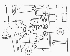
Fig.49
- Install the pressure regulating-valve (11), oil cooler pipe connectors
and the speed and calibration sensors in the housings.
Overhaul a MF 8250, 8260, 8270 tractor speed clutch train
- All speed clutch trains are disassembled in the same manner.
- All speed clutch trains are composed of two clutch packs.
The sets of speed Massey Ferguson 8240, 8250, 8270 tractor clutches are
identified thus:
- clutches A and 2 - 2nd stage shaft
- clutches B and R - 3rd stage shaft
- clutches C and 1 - 4th stage shaft
- For more details on the fitting of each shaft, see the inspection the
transmission components.
- Using a clutch train sling (ATP 3021), remove the speed clutch to be
repaired from the pinion block support tool. Place the clutch train on a
clean workbench and turn
the groove of the seal ring upwards.
Take care that the gear train is properly supported to avoid it toppling
and damaging the pinions.
- Install a split bearing extractor (OEM 4175 or equivalent) on the
bearings. The split bearing extractor must be fitted so that its flat
surface is turned towards the pinion.
-
Tighten the tightening bolts of the extractor until the bearing begins
to extract.
- Hook the pinion extractor below the split bearing extractor and
extract the bearing from the shaft by pulling.
- Remove the circlip from the shaft.
- Place the extractor (ATP 3030) on the pinion and tighten the bolt. To
be able to remove the pinion from the shaft, the extractor must be
tightened around the external
diameter of the pinion.
- In some cases, the main sleeve is necessary and
must be fitted beneath the pinion. Place the extractor by hooking it
beneath the sleeve and
extract the pinions and the bearing from the shaft by pulling.
-
To select the extraction sleeve that matches the pinion, see the pages
relating to the clutch trains.
- Remove circlip, closing plate, thrust plates and friction plates.
- Install a suitable extractor on the bearing of the inside pinions and
remove the latter from the shaft.
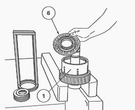
Fig.50
- Place the clutch train in a press. Fit tool ATP 3002 on the Belleville
washers. Compress the washers, remove the circlip and release the
pressure on the washers.
- Remove the Massey Ferguson MF 8250, 8260, 8270 tractor clutch train
from the press and remove the locking washer from circlip (11) and the
Belleville washers
(10).
- Remove the oil seal washer (9) that lies between the Belleville
washers (10) and the clutch piston (6).
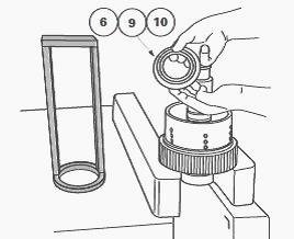
Fig.51
- Once the Belleville washers are removed, inject compressed air into
the clutch oil supply channel near the seal ring on the shaft (24) or
(25). This will eject the piston
from the clutch housing (1).
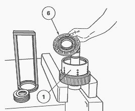
Fig.52
- Disassemble the opposite end of the shaft in the same manner.
The best method to maintain the shaft in a vertical position is to have
a 3” (76 mm) diameter hole in the workbench to recieve the shaft.
________________________________________________________________________________
 SPECS
 LOADERS
 MAINTENANCE
 PROBLEMS
________________________________________________________________________________________
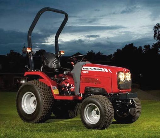 MF 1523
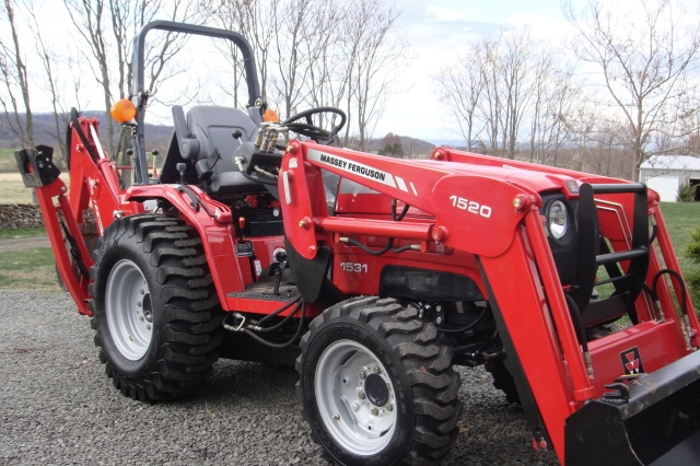 MF 1531
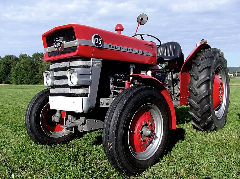 MF 135
 MF 1547
 MF 1635
________________________________________________________________________________________
 231
 231S
 235
 240
 241
________________________________________________________________________________________
_______________________________________________________________________________________
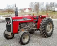 255
 265
 274
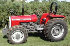 285
 375
________________________________________________________________________________________
________________________________________________________________________________________
 916X Loader
 921X Loader
 926X Loader
 931X Loader
 936X Loader
________________________________________________________________________________________
 941X Loader
 946X Loader
 951X Loader
 956X Loader
 988 Loader
________________________________________________________________________________________
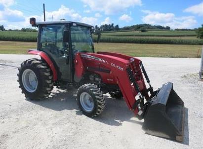 1655
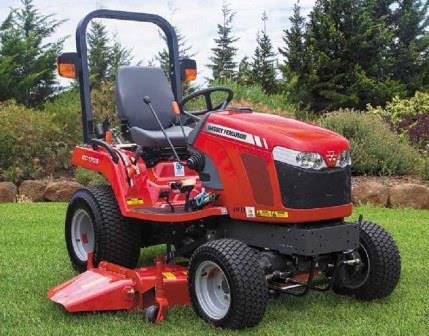 GS1705
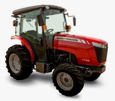 1742
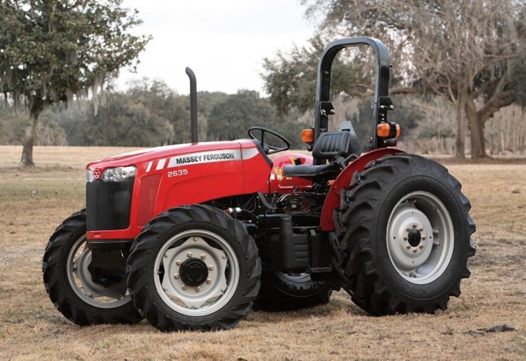 2635
 4608
________________________________________________________________________________________
 1080
 1100
 2615
 3050
 3060
________________________________________________________________________________________
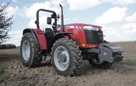 4708
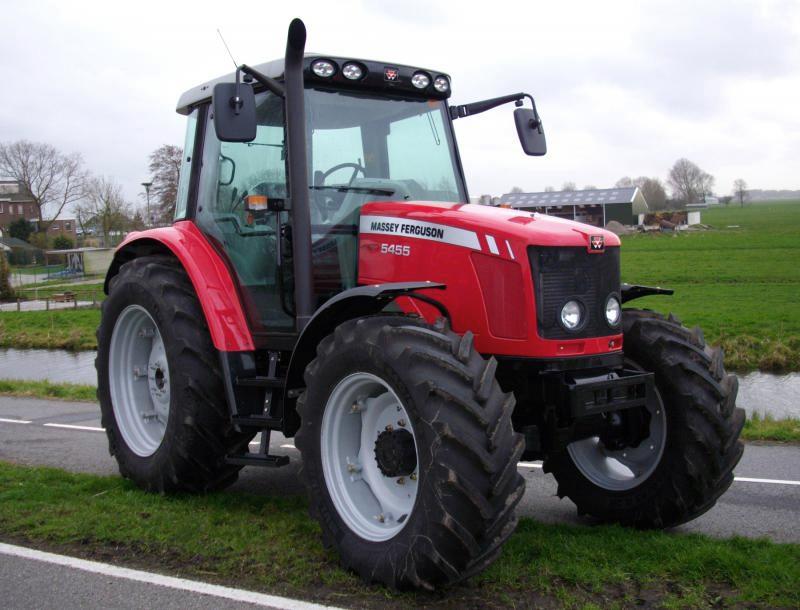 5455
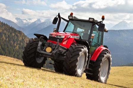 5450
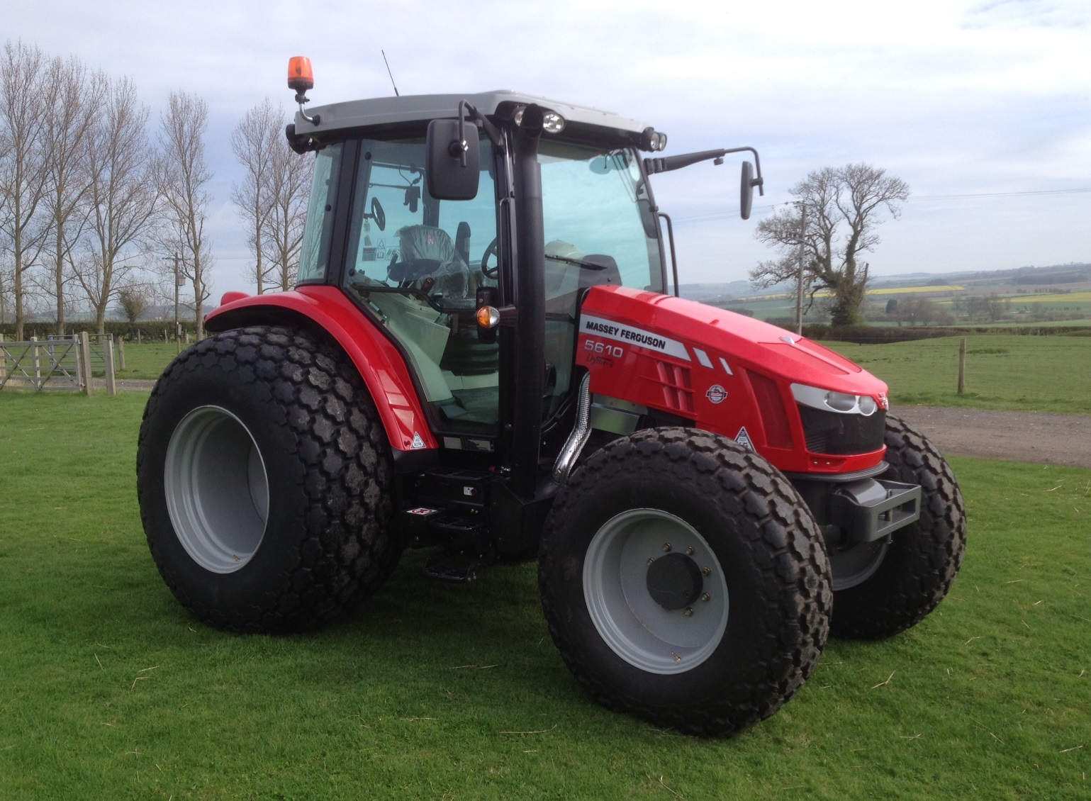 5610
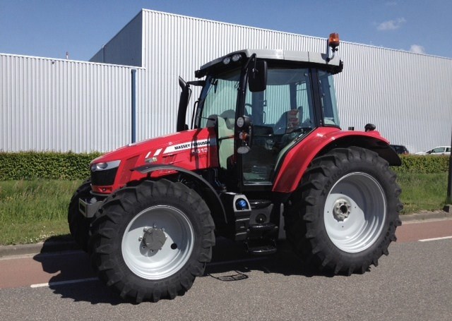 5613
________________________________________________________________________________________
 DL95 Loader
 DL100 Loader
 DL120 Loader
 DL125 Loader
 DL130 Loader
________________________________________________________________________________________
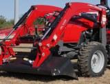 DL135 Loader
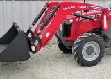 DL250 Loader
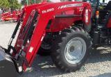 DL260 Loader
 L90 Loader
 L100 Loader
________________________________________________________________________________________
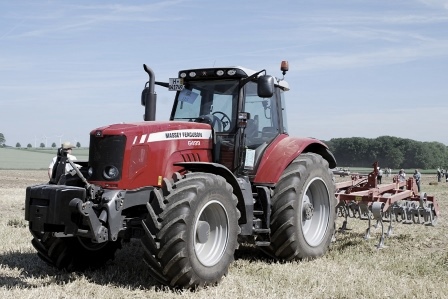 6499
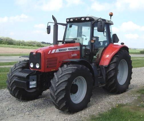 7480
 7618
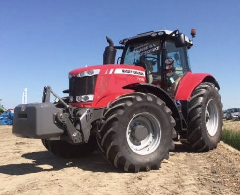 7726
 1533
________________________________________________________________________________________
 2604H
 2607H
 4455
 4610M
 4710
________________________________________________________________________________________
 L105E Loader
 L210 Loader
 1014 Loader
 1016 Loader
 1462 Loader
________________________________________________________________________________________
 1525 Loader
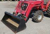 1530 Loader
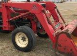 232 Loader
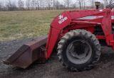 838 Loader
 848 Loader
________________________________________________________________________________________
 5712SL
 6713
 6715S
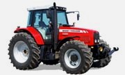 7475
 7615
________________________________________________________________________________________
 7716
 7724
 8240
 8650
 8732
________________________________________________________________________________________
 246 Loader
 1036 Loader
 1038 Loader
 1080 Loader
 856 Loader