________________________________________________________________________________
Kubota BX23, BX23S - 54,60 Inch Mower Deck
Kubota RCK54, RCK60 Mower link
Structure of lifting mechanism of mower
The lifting of RCK54, RCK60 Mower Deck is performed by the hydraulic system installed on Kubota BX23, BX23S tractor. The mower should be kept lift when traveling. When the position control lever is moved to LIFT position, the lift arm is lifted up by the oil pressure of hydraulic system, and the rear lift link (L.H.) is pulled rearward. Therefore, rear lift links rotate and the mower is lifted by the lift links and rear links. As this link system is a parallel linkage, the mower can be kept parallel at every position.
Mounting front link
Place all front link and frame link under the tractor. Attach the stay link with the nut on the tractor front frame. Stay link nut - 43.3 to 50.3 Nm / 32 to 37 lbf-ft. Attach the front link to the stay link with joint pin, washer and snap pin. Before attaching the mower links, adjust lengths (L1) to 22 mm.
Mounting frame link
Place blocks below the frame link if one person does the setting.
Heights of blocks are recommended value for attaching. Start engine. Set
the cutting height to 0 and lower the frame link. Then stop the engine.
Attach the frame link to the link arm. Joint the front link and frame
link with joint pin and snap ring. Attach the universal joint to Kubota
BX23, BX23S tractor. Adjusting mower link - Move the hydraulic control
lever rearward to raise the mower to the highest position. Stop the
engine and remove the key. Adjust the left side links with bolt so that
the clearance is as follows. Clearance between stopper and rear link 0
to 0.5 mm / 0 to 0.01 in.
Kubota RCK54, RCK60 Mower Deck Setting up
Assembling 54-inch mower deck
Place the mower on blocks. Attach all the anti-scalp rollers to the arms of the deck. Put clevis pins from outside and snap rings inside in the F position. 4.5 holes (X) must be visible. Attach the discharge deflector to the deck with the spring, discharge pin and cotter pin. Setting mower - Check all functions work correctly. Remove the front loader, front attachment and 3 point hitch attachment. Adjust all the anti-scalp rollers to the F position. 4.5 holes (X) must be visible. Unlock the lever to lift up the rear anti-scalp roller. Pull the L-pin and extend the ramp to front and rear sides.
Setting Kubota BX23, BX23S tractor
Make sure that the frame link is lifted up to the TOP position when tractor is traveling without mower. Stop the tractor behind the mower. Set the parking brake. Set the cutting height to 0 and lower the frame link. Then stop the engine. Make sure that the rear lock is unlocked. Make sure that the universal joint is in rear position. Make sure that the frame link is fully down.
Mounting 60-inch mower deck
Start the engine and engage 4WD. Set the range gear shift lever to LOW.
Release the parking brake. With the right front tire, make a driving
target to the guide. Drive over the ramp of mower along the guide. Keep
the front tire side touching the guide rod. Just after the Kubota BX23,
BX23S tractor drove over the mower, stop the engine. Make sure frame
link is connected to mower. Set the parking brake. Lock the rear lock.
Set the PTO select lever to Rear-PTO position. Connect the universal
joint by the lever guide. Lock the lever guide by the lock lever. Set
the PTO select lever to Mid-PTO position. Put front and rear ramps back
to the ramp bracket. Lock the L-pin. Start the engine. Lift up the mower
to the TOP position. Lock the dial gauge and set the parking brake. And
then, stop the engine. Lock the rear anti-scalp roller. Adjust the
anti-scalp roller.
Kubota RCK54, RCK60 Mower Deck - Cutting height
Adjusting front and rear cutting height
Turn the cutting height control dial to 2.0 and adjust the anti-scalp roller's height to factory specified clearance between the rollers and the ground. Clearance between rollers and ground - 6.0 to 13 mm / 0.25 to 0.50 in. Align the ends of the right side blade towards the front and rear of the machine. Turn blade by hand in either direction. Adjust (L1) of the front links with lock nuts so that (A) is within factory specification. Difference between front tip and rear tip of blade 0.0 to 5.0 mm / 0.0 to 0.20 in. To adjust (L1), loosen lock nuts then turn lock nuts. Rotate both lock nuts at the same time to set L.H. and R.H. in even length. Tighten lock nuts securely. Front link lock nut 60 to 70 Nm / 45 to 51 lbf-ft.
Adjusting left and right cutting height
Operate the hydraulic control lever rearward to raise the mower deck to the highest position. Stop the engine and remove the key. Turn the cutting height control dial to the desired height. Set the anti-scalp roller's height to keep clearance between rollers and the ground inside specification shown below. Clearance between rollers and ground - 6 to 13 mm / 0.2 to 0.5 in. Lower the mower deck by moving the hydraulic control lever forward. Turn left blade by hand parallel to Kubota BX23, BX23S tractor axle and turn right blade parallel to axle to measure from the outside blade tip at and to the level surface. The difference between measurement should be less than the factory specification.
Difference between left tip and right tip of blade
Less than 3 mm / 0.12 in. If the difference between measurement is more than the factory specification, loosen the lock nut of the left side. Adjust the cutting height fine turning bolts so that the difference between measurement is less than the factory specification. Then lock the nut.
Adjusting cutting height
To reduce the stepped difference in cutting height when
mowing rolling terrain, follow the procedure below. To set the cutting
height, move the hydraulic control lever rearward to raise the mower to
the highest position. Turn the cutting height control dial to adjust
height. Set the anti-scalp roller's height as shown to keep clearance
between rollers and ground. Clearance between rollers and ground - 6.0
to 13 mm / 0.25 to 0.50 in. Lower the mower deck by moving the hydraulic
control lever forward. Use the higher settings for mowing in a rough
area or when mowing tall grass. Lower settings should be used only for
smooth lawns where short grass is desired. To set the cutting height,
move the hydraulic control lever rearward to raise the mower to the
highest position. Turn the cutting height control dial to adjust height.
Set the anti-scalp roller's position to have the same cutting height.
Kubota BX23, BX23S Tractor - Mower blade
Checking mower blade
Check the cutting edge of mower blade. Sharpen the cutting edges. To sharpen the mower blades by yourself, clamp the mower blade securely in a vise and use a large mill file along the original bevel. To balance the mower blade, place a small rod through the center hole and check to see if the blade balance evenly. File heavy side of the blade until it balance out even. Replace the mower blades. Removing ramps and belt covers RCK54-26BX and RCK60-26BX - Remove left and right ramp bracket pins. Remove left and right ramps. Remove the left and right belt covers.
Removing mower blades
To remove the blade securely, wedge a block of wood between one blade and the mower deck in such position that it will hold the blade safely while loosing or tightening the blade screw. Turn over the mower. Remove the blade mounting bolt, lock washer, cup washers, mower blade and spindle guard from the spindle holder. Install the blade in position together with the dust cover and the cup washers. Tighten them up with the bolt. Blade mounting bolt - 103 to 117 Nm / 76.0 to 86.7 lbf-ft. Removing blade boss - Remove the external snap ring. Remove the blade boss.
Removing outer pulley and blade shaft
Remove the outer pulley mounting nut, and
remove the outer pulley. Remove the outer pulley holder mounting nut,
and remove the outer pulley holder. Remove the oil seal and tap out the
blade shaft with the ball bearing, being careful not to damage the
grease fitting. Remove the ball bearing, and collar from the blade
shaft. Remove the ball bearing, and oil seal.
Gear box and mower belt
Removing gear box and mower belt
Turn over the Kubota RCK54, RCK60 Mower Deck. Remove the mower belt from the tension pulley. Remove the left and right gear box mounting screws and remove the gear box from the mower deck. Gear box mounting screw - 78 to 90 Nm / 58 to 66 lbf-ft. Disassembling gear box - Remove the drain plug, and drain the gear box oil. Remove the center pulley with a puller, and remove the feather key on the bevel gear shaft. Remove the gear box cap. Remove the oil seal, internal snap ring and shim. Tap out the pinion shaft with the ball bearing, and remove the bevel gear. Remove the ball bearing and shims (if installed). Remove the external snap ring, and draw out the bevel gear shaft. Remove the bevel gear, ball bearing, shim and oil seal.
Checking mower belt
Check to see the mower belt. Replace the mower belt with a new one, if there is found surface split at more than three positions. After setting the gear box bracket mounting screws on the deck without tightening, then mount the other screws on the gear box. And finally tighten them. Dismount the mower from Kubota BX23, BX23S tractor. Remove the left and right ramp brackets. Remove the left and right hand belt cover from the mower deck. Clean around the gear box. Remove the gear box bracket (right) which mounts the gear box to the mower deck. Remove the mower belt from the tension pulley. Slip the mower belt over the top of the gear box. To install a new belt, reverse the above procedure. Gear box bracket mounting bolt and nut - 78 to 90 Nm / 58 to 66 lbf-ft. Gear box mounting screw - 78 to 90 Nm / 58 to 66 lbf-ft.
Removing center pulley holder
Remove the center pulley holder bolt / center pulley nut. Remove the upper oil seal and lower oil seal. Remove the internal snap ring and ball bearing. When reassembling the center pulley holder, gear box and gear box bracket, tighten the bolts and nuts in the order as below, to prevent the incline the gear box. Tighten the reamer screw to the gear box first, then tighten the reamer bolts and nut to the center pulley holder with specified torque. Tighten the gear box screws to the gear box and then tighten the center pulley holder bolts and nut with specified torque. Replace the oil seals with new ones. Install the reamer screw / reamer bolt at their original positions as shown in the figure. Be sure to fix the O-rings to the original position. Center pulley holder bolt and nut 78 to 90 Nm / 58 to 66 lbf-ft.
Kubota BX23, BX23S Tractor - Mower ServicingAdjusting turning torque of pinion shaft - Set the blade screw for the blade shaft to measure the turning torque. Turn the blade screw clockwise with torque wrench and measure the turning torque. Turning torque - Less than / 0.7 Nm 0.52 lbf-ft. Thickness of adjusting shims - 0.2 mm 0.0079 in. / 0.3 mm 0.0118 in. Thickness of adjusting shims - 0.2 mm 0.0079 in. / 0.3 mm 0.0118 in. Adjusting backlash between bevel gears - Remove the gear box cap. Place the plastigauges or wire of solder the bevel gear on the input shaft. Turn the input shaft. Remove the plastigauges or wire of solder, and measure the thickness with the gauge or an outside micrometer.
- Kubota RCK54, RCK60 mower servicing
- Kubota LA340 Loader for BX23, BX23S tractors
- Kubota LA240 Loader for BX24, BX25, BX25D models
- Kubota BT603 backhoe for BX23, BX23S models
- Kubota BT601 backhoe for BX24, BX25, BX25D tractors
________________________________________________________________________________
________________________________________________________________________________________
________________________________________________________________________________________
________________________________________________________________________________________
________________________________________________________________________________________
________________________________________________________________________________________
________________________________________________________________________________________
________________________________________________________________________________________
________________________________________________________________________________________
________________________________________________________________________________________
________________________________________________________________________________________
________________________________________________________________________________________
________________________________________________________________________________________
________________________________________________________________________________________
________________________________________________________________________________________
________________________________________________________________________________________
________________________________________________________________________________________
________________________________________________________________________________________
________________________________________________________________________________________
________________________________________________________________________________________
________________________________________________________________________________________
________________________________________________________________________________________
________________________________________________________________________________________
________________________________________________________________________________________
________________________________________________________________________________________
________________________________________________________________________________________
________________________________________________________________________________________
________________________________________________________________________________________
________________________________________________________________________________________

 SPECIFICATIONS
 LOADERS
 ENGINES
 INSTRUCTIONS
 PROBLEMS
 B2320
B2320 B2630
B2630 B2920
B2920 B3300SU
 BX2360
 L245
L245 L260
L260 L275
L275 L285
L285 L305
L305 D662
D662 D722
D722 D750
D750 D782
D782 D850
D850 LA302
LA302 LA304
LA304 LA340
LA340 LA344
LA344 LA351
LA351 BX2660
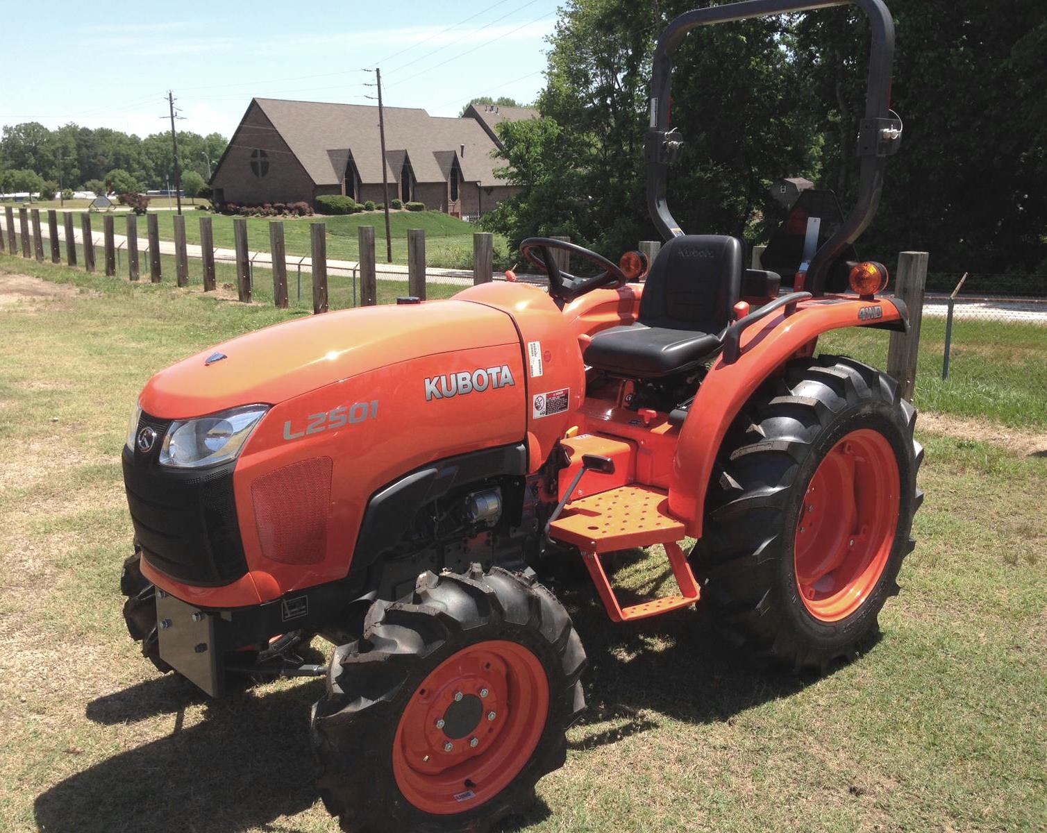 L2501
L2501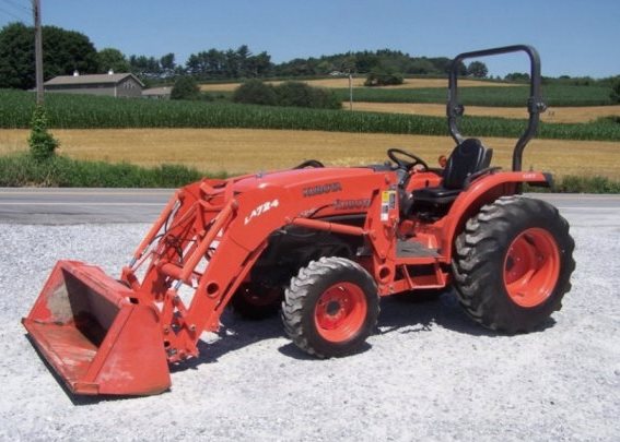 L3240
L3240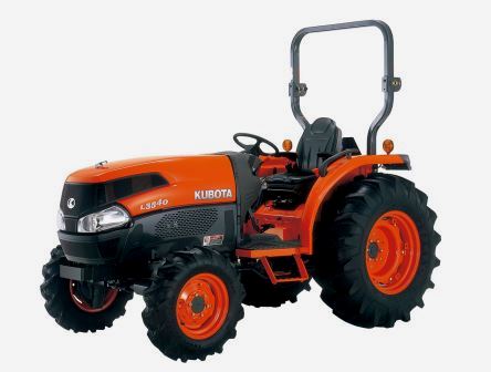 L3540
L3540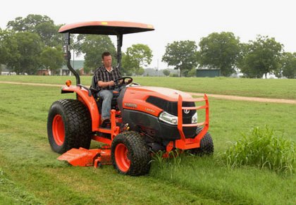 L3940
L3940 D902
D902 D905
D905 D950
D950 D1005
D1005 D1100
D1100 B1630
B1630 BF400
BF400 BF400G
 LA181
LA181 LA203
LA203 LA211
LA211 LA243
LA243 LA271
LA271 LA272
LA272 LA301
LA301 L175
L175 L185
L185 L210
L210 L225
L225 L235
L235 D1105
D1105 D1503
D1503 D1703
D1703 D1803
D1803 V1200
V1200 L4400
L4400 L4600
L4600 L5040
L5040 L5740
L5740 MX4700
 LA352
LA352 LA364
LA364 LA401
LA401 LA402
LA402 LA434
LA434 LA463
LA463 LA481
LA481 LA482
LA482 LA504
LA504 V1205
V1205 V1305
V1305 V1505
V1505 V2203
V2203 V2403
V2403 B2710
B2710 BX23S
BX23S B3350
B3350 BX1880
 L4701
L4701 LA513
LA513 LA514
LA514 LA524
LA524 LA525
LA525 LA534
LA534 LA555
LA555 LA680
LA680 LA681
LA681 LA682
LA682 LA703
LA703 Z482
Z482 Z602
Z602 Z750
Z750 Z1100
Z1100 Z1300
Z1300 M100GX
 M135GX
 M6040
M6040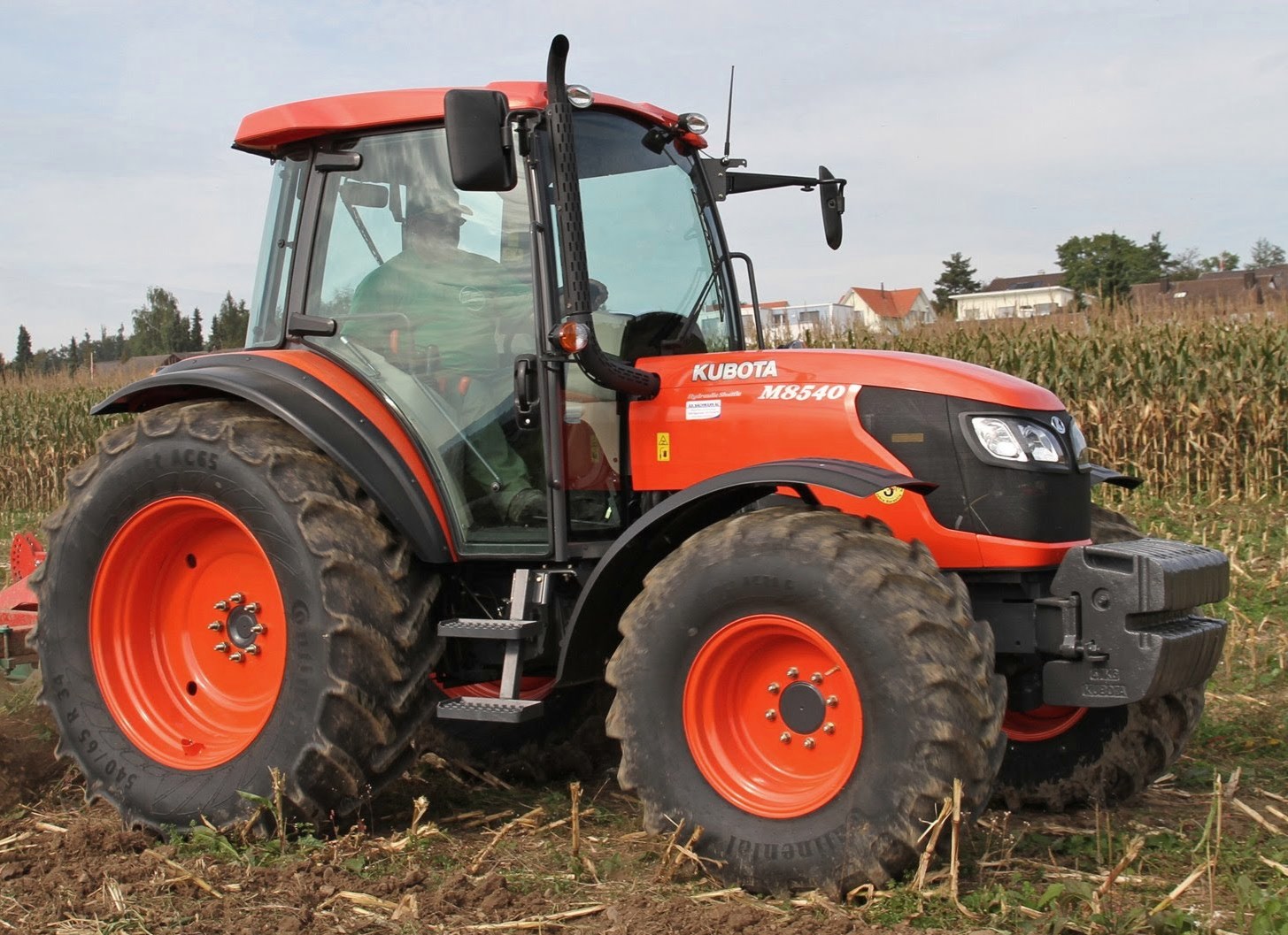 M8540
M8540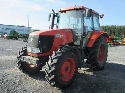 M95X
M95X LA714
LA714 LA723
LA723 LA724
LA724 LA764
LA764 LA765
LA765 LA805
LA805 LA844
LA844 LA852
LA852 LA853
LA853 LA854
LA854 M5-091
 BX2680
 MX5200
 BX2380
 L3901
L3901 LA1002
 LA1055
 LA1065
 LA1153
 LA1154
 LA1251
 LA1301S
 LA1353
 LA1403
 LA1601S
 LA1854
 LA1944
 LA1953
 LA2253
 LM2605