________________________________________________________________________________
Kubota BX24, BX25, BX25D - BT601 backhoe
Kubota BX24, BX25, BX25D - BT601 backhoe Hydraulic Valve
Inlet - This section has P and T ports. The P port is connected to the
OUTLET port of Kubota BX24, BX25, BX25D tractor connected by the quick
coupler. The T port is connected to the transaxle case by the quick
coupler. Control Valve Section - The control valves are of 3 positions,
6 connections, no detent, spring center type. These valves have A and B
ports and control oil flow to each cylinders. These are consisting of a
valve housing, spool, load check valve, overload relief valve, etc.
Outlet Section - This section has P.B. port which is connected to the INLET port of hydraulic block or front loader control valve. Pressure-fed oil from the hydraulic pumps are delivered into P port in the inlet section. As the load check valves are kept closed in the neutral position. oil flows along the notched section of the spools to the P.B port through the neutral passage. Then the oil is fed to the front loader valve or transaxle case and pipe from the P.B port.
Bucket
(Roll-back) - When the dipperstick and bucket lever is moved to the left
to set to the "ROLL-BACK" position, the spool of the bucket control
valve moves to the right. which forms oil passage between bridge passage
and B1 port, and between A1 port and T port. The pressure-fed oil from
the P port opens the load check valve and flows to B1 port to extend the
bucket cylinder. Return oil from the bucket cylinder returns to the
transmission case through the A 1 port. low pressure passage and T port.
Bucket (Dump) - When the dipperstick and bucket lever is moved to the
right to set to the "DUMP" position, the spool of the bucket control
valve moves to the left, which forms oil passage between bridge passage
and Ai port, and between B1 port and T port. The pressure-fed oil from
the P port opens the load check valve and flows to A1 port to retract
the bucket cylinder. Return oil from the bucket cylinder returns to the
transmission case through the B1 port, low pressure passage and T port.
Boom (Up) - When the boom and swing lever is pulled to the backward to set to the "UP" position, the spool of the boom control valve moves to the left, which forms oil passage between bridge passage and B5 port, and between A5 port and T port. The pressure-fed oil from the P port opens the load check valve and flows to B5 port to retract the boom cylinder. Return oil from the boom cylinder returns to the transmission case through the AS port, low pressure passage and T port.
Boom (Down) -
When the boom and swing lever is pulled to the forward to set to the
"DOWN" position, the spool of the boom control valve moves to the right,
which forms oil passage between bridge passage and AS port, and between
B5 port and T port. The pressure-fed oil from the P port opens the load
check valve and flows to AS port to extend the boom cylinder. Return oil
from the boom cylinder returns to the transmission case through the B5
port, low pressure passage and T port.
Kubota BX24, BX25, BX25D - BT601 backhoe Overload Relief Valve
Overload relief valve in this control valve is a combination valve
combining a relief operation and anticavitation operation. Relief
Operation - When the control valve is in the neutral position, both
cylinder ports of control valve are blocked by the spool. If an external
load is imposed on the cylinder, pressure builds in the circuit. When
the pressure exceeds the set level of the overload relief vale, the
relief valve opens and the oil returns to tank. In this way, the
hydraulic circuit and actuator are protected from excessive pressures.
Anti-cavitation Operation - Overload relief valve also has anti-void
function. If a negative pressure takes place in the circuit, the oil is
fed from the tank to eliminate the negative pressure. When the actuator
port pressure is lower than the setting - The cylinder port HP is
applied to the seat B in the following route: first through the throttle
a of the piston poppet (1) built in the relief valve poppet, second
through the spring chamber A, and then through the circular clearance
between the adjusting screw and the piston poppet. This cylinder port HP
works to open the pilot poppet. Because the piston spring has not
reached the set pressure, however, the valve stays shut. In this way the
seat remains intact and the relief valve poppet stays shut.
Kubota BX24, BX25, BX25D - Mounting Pin and Mounting BT601 Backhoe
Make sure both hoses are firmly connected before starting the engine.
Start the engine. Stand beside the rear wheel. Move the boom to fully
raising position and raise Kubota BT601 backhoe by operating the stabilizers
until the mount bar on the backhoe main frame are slightly higher than
the tractor main frame support hooks. If the support hooks are not
parallel to the mount bars, adjust with the stabilizers. Move Kubota
BX24, BX25, BX25D tractor backward until the support hooks on the
tractor main frame are just beneath the mount bar on the backhoe main
frame. Lower the mount bar onto the support hooks by operating the
stabilizer and boom control levers.
Move the boom slowly to the lowering
position, and engage the guide plates of the main frame to the bosses of
sub frame. Then raise the rear wheels slightly by operating the boom to
the lowering direction. Shut off the engine. Reinstall the mounting
pins, and insert the slide bar of the mounting pins to the hole of the
main frame. Be careful not to catch the hydraulic hoses between backhoe
frame and tractor while mounting the backhoe. Move Kubota BX24, BX25,
BX25D tractor loader backhoe to an open area and cycle all backhoe
functions. This will check their operation and flow oil back through the
system, filtering it and refilling each circuit. Check the hydraulic oil
level before putting the backhoe into full operation.
Disassembling Kubota BT601 backhoe
Bucket - Remove the bucket from the dipper stick.
Dipperstick and Bucket Cylinder - Bucket, dipperstick, boom, swing, and stabilizer cylinder consists of cylinder head, piston rod, cylinder tube, piston and other parts. They are single-rod double acting cylinders in which the reciprocating motion of the piston is controlled by hydraulic force applied to both of its ends. Remove the pins and remove the bucket link and guide link. Disconnect the hydraulic hoses and remove the bucket cylinder. Remove the pins and remove the dipperstick. To prevent from the damage of hydraulic hoses, set the wooden block etc. between dipperstick cylinder and boom. Lock the locking nuts to setting bolts at position where the setting bolt may still be rotated. Replace the spacers at their original position.
Dipperstick Cylinder, Boom, Boom Cylinder and Hoses - Disconnect the hydraulic hoses and remove the dipperstick cylinder. Remove the pins and remove the boom cylinder. Remove the pin and remove the boom. Remove the hydraulic hoses from the control valve. Lock the locking nuts to setting bolts at position where the mounting bolt may still be rotated. Connect the hydraulic hoses at their original positions and be sure to connect the hose angle as indicated table below.
Swing Frame - Disconnect the swing cylinder rods from swing frame. Remove the swing frame from main frame. Lock the locking nuts to setting bolts at position where the setting bolt may still be rotated. Reinstall the thrust washers at their original positions.
Swing Cylinder - Remove the swing cylinder bottom pin. Disconnect the hydraulic hoses. Remove the swing cylinder.
Stabilizers and Stabilizer Cylinder - Remove the pins and remove the stabilizer cylinder with hydraulic hoses. Remove the pin and remove the stabilizer. Lock the locking nuts to setting bolts at position where the setting bolt may still be rotated.
Lever Support and Valve - Remove the cover. Disconnect the control lever rods of valve side. Remove the lever support with control levers. Disconnect the hydraulic hoses. Remove the control valve. Connect the hydraulic hoses at their original portions and be sure to connect the hose angle as indicated table below.
Backhoe
Main Frame and Hydraulic Hose - Hoist the backhoe main frame and remove
the mount pins. Remove the three hydraulic hoses. Separate the main
frame from Kubota BX24, BX25, BX25D tractor frame.
Kubota BT601 backhoe - Servicing specifications (Clearance)
Boom Cylinder Rod Pin to Cylinder Bushing - 0.060
to 0.185 mm / 0.002 to 0.007 in.
Boom Support, Oipperstick Fulcrum Pin to Bushing - 0.140 to 0.180 mm /
0.006 to 0.007 in.
Oipperstick Cylinder Rod Pin to Cylinder Bushing - 0.060 to 0.185 mm /
0.002 to 0.007 in.
Bucket Fulcrum Pin, Bucket Cylinder Pin, Bucket Guide Link Pin to
Bushing - 0.204 to 0.315 mm.
Boom Fulcrum Pin to Swing Frame Bushing - 0.140 to 0.180 mm / 0.006 to
0.007 in.
Main Frame Fulcrum Pin to Bushing - 0.070 to 0.130 mm / 0.003 to 0.005
in.
Swing Cylinder Rod Pin to Cylinder Bushing - 0.108 to 0.259 mm / 0.004
to 0.010 in.
All functions inoperative (Front loader
is OK) - Quick coupler disconnected.
All functions including front loader, are inoperative -
Insufficient transmission fluid. Relief valve spring damaged. Hydraulic
pump malfunctioning. Oil filter clogged.
Hydraulic oil overheats - Continuous operation against
relief. Transmission fluid improper brand and viscosity. Relief valve
mis-adjusted. Insufficient transmission fluid. Oil filter clogged.
Individual cylinder circuit weak or inoperative (Others OK)
- Valve spool not moving fully. Valve spool stick (especially when
warm). Overload relief valve mis-adjusted. Piston seal ring worn or
damaged. Cylinder tube worn or damaged. Oil leaks from joint. Hydraulic
hose damaged. Dust in overload relief valve.
Excessive cylinder movement - Piston seal ring worn or
damage. Excessive valve spool to bore tolerance. Hydraulic hose or
fitting damaged. Hydraulic hose or fitting loose. Cylinder tube worn or
damaged.
Insufficient cylinder speed - Engine rpm too low.
Hydraulic pump malfunctioning. Relief valve pressure too low.
Insufficient transmission fluid.
- Kubota 54/60 inch mower service
- Kubota RCK54, RCK60 mower servicing
- Kubota LA340 Loader for BX23, BX23S tractors
- Kubota LA240 Loader for BX24, BX25, BX25D models
- Kubota BT603 backhoe for BX23, BX23S models
________________________________________________________________________________
________________________________________________________________________________________
________________________________________________________________________________________
________________________________________________________________________________________
________________________________________________________________________________________
________________________________________________________________________________________
________________________________________________________________________________________
________________________________________________________________________________________
________________________________________________________________________________________
________________________________________________________________________________________
________________________________________________________________________________________
________________________________________________________________________________________
________________________________________________________________________________________
________________________________________________________________________________________
________________________________________________________________________________________
________________________________________________________________________________________
________________________________________________________________________________________
________________________________________________________________________________________
________________________________________________________________________________________
________________________________________________________________________________________
________________________________________________________________________________________
________________________________________________________________________________________
________________________________________________________________________________________
________________________________________________________________________________________
________________________________________________________________________________________
________________________________________________________________________________________
________________________________________________________________________________________
________________________________________________________________________________________
________________________________________________________________________________________

 SPECIFICATIONS
 LOADERS
 ENGINES
 INSTRUCTIONS
 PROBLEMS
 B2320
B2320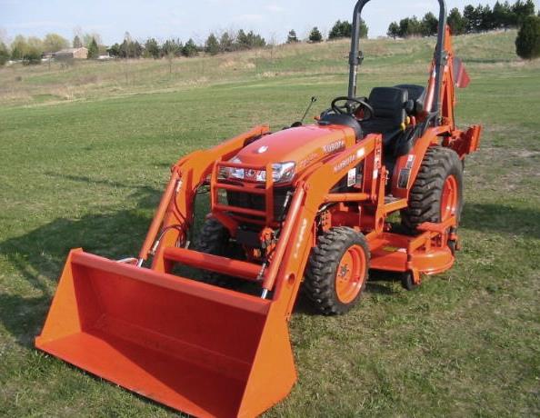 B2630
B2630 B2920
B2920 B3300SU
 BX2360
 L245
L245 L260
L260 L275
L275 L285
L285 L305
L305 D662
D662 D722
D722 D750
D750 D782
D782 D850
D850 LA302
LA302 LA304
LA304 LA340
LA340 LA344
LA344 LA351
LA351 BX2660
 L2501
L2501 L3240
L3240 L3540
L3540 L3940
L3940 D902
D902 D905
D905 D950
D950 D1005
D1005 D1100
D1100 B1630
B1630 BF400
BF400 BF400G
 LA181
LA181 LA203
LA203 LA211
LA211 LA243
LA243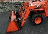 LA271
LA271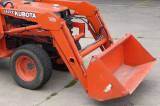 LA272
LA272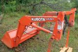 LA301
LA301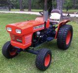 L175
L175 L185
L185 L210
L210 L225
L225 L235
L235 D1105
D1105 D1503
D1503 D1703
D1703 D1803
D1803 V1200
V1200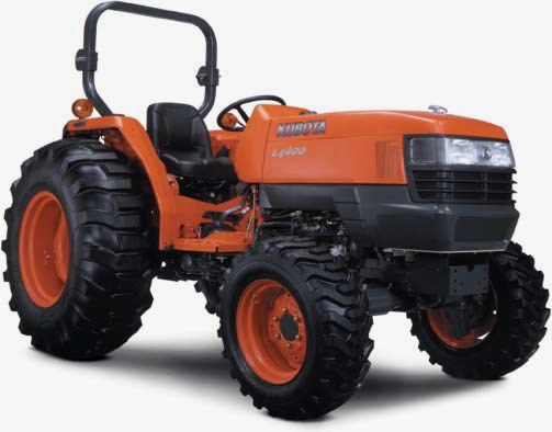 L4400
L4400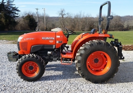 L4600
L4600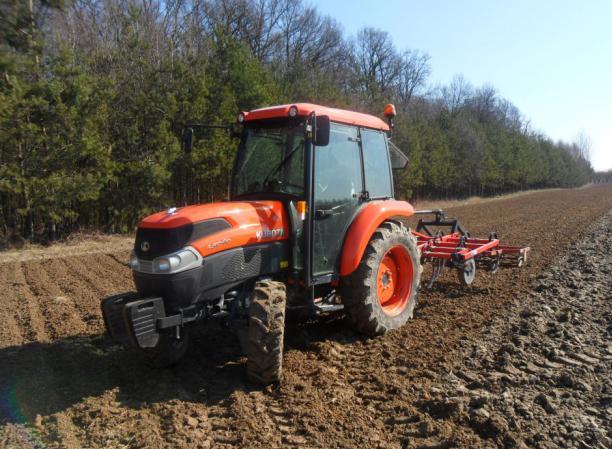 L5040
L5040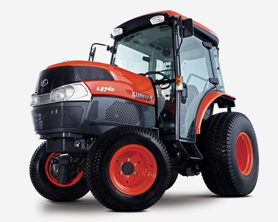 L5740
L5740 MX4700
 LA352
LA352 LA364
LA364 LA401
LA401 LA402
LA402 LA434
LA434 LA463
LA463 LA481
LA481 LA482
LA482 LA504
LA504 V1205
V1205 V1305
V1305 V1505
V1505 V2203
V2203 V2403
V2403 B2710
B2710 BX23S
BX23S B3350
B3350 BX1880
 L4701
L4701 LA513
LA513 LA514
LA514 LA524
LA524 LA525
LA525 LA534
LA534 LA555
LA555 LA680
LA680 LA681
LA681 LA682
LA682 LA703
LA703 Z482
Z482 Z602
Z602 Z750
Z750 Z1100
Z1100 Z1300
Z1300 M100GX
 M135GX
 M6040
M6040 M8540
M8540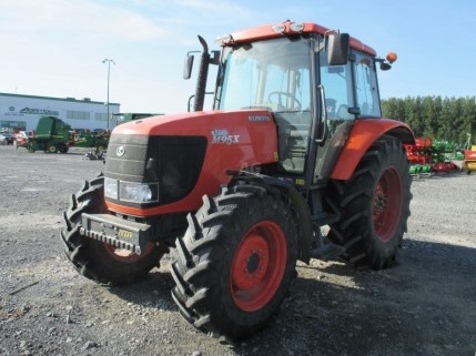 M95X
M95X LA714
LA714 LA723
LA723 LA724
LA724 LA764
LA764 LA765
LA765 LA805
LA805 LA844
LA844 LA852
LA852 LA853
LA853 LA854
LA854 M5-091
 BX2680
 MX5200
 BX2380
 L3901
L3901 LA1002
 LA1055
 LA1065
 LA1153
 LA1154
 LA1251
 LA1301S
 LA1353
 LA1403
 LA1601S
 LA1854
 LA1944
 LA1953
 LA2253
 LM2605