________________________________________________________________________________
Kubota BX23, BX23S, BX24, BX25, BX25D Steering - Adjust and Service
Kubota BX23, BX23S, BX25, BX25D Steering - Check and adjust
Checking relief valve operating pressure - After setting a pressure
gauge, be sure to bleed air. Note that the pressure value changes by the
pump action of the power steering controller when the steering operation
is continued after the steering wheel is lightly locked and accurate
relief valve pressure cannot be measured. Disconnect the power steering
hose L (or R) from steering controller, and set a pressure gauge and
hose. Hose and adapter size 9/16-18 UNF, 37 degrees flare. Start the
engine and set at maximum speed. Fully turn the steering wheel to the
left (or right) to check the feeling which the steering wheel lightly
locks. Read the relief valve operating pressure when the steering wheel
to the above-mentioned lock position by operation force. Operation force
(Steering wheel) Approximate - 9.8 N / 2.2 lbf. Relief valve operating
pressure (Kubota BX23, BX23S, BX24, BX25, BX25D) - 8.34 to 8.82 MPa /
1210 to 1280 psi.
Kubota BX23, BX23S, BX24, BX25, BX25D Steering - Disassembling and assembling
Power steering cylinder
Removing adapter and
tie-rod - Remove the cylinder hose adapters. Remove the tie-rods from
piston rod. Remove the cylinder holder and internal snap ring. After
reassembling the tie-rod, be sure to adjust the toe-in. Tie-rod screw
(Kubota BX23, BX23S, BX24, BX25, BX25D) - 74 to 84 Nm / 55 to 62 lbf-ft.
Disassembling steering cylinder - Carefully clamp the cylinder in a
vise. Push one of the guide assembly to inside of cylinder tube. Drill a
hole on the cylinder tube just over the snap ring. Hole - 2.5 mm
diameter / 0.098 in. diameter. Take a little screwdriver and lift off
the snap ring from its groove. Simultaneousness support this action by
pushing from the outside of the cylinder tube with another little
screwdriver or another tool. Push out the piston rod assembly and take
off the guide assembly. Seals must be exchanged after disassembling.
Apply transmission fluid to the exchanged seals. Enter the piston rod
and block the guide assemblies with the snap rings.
Separating power steering controller
Removing battery - Remove the
under panel. Disconnect the negative cable from the battery. Disconnect
the positive cable from the battery and remove the battery. Removing
steering wheel - Remove the steering wheel cap. Remove the steering
wheel mounting nut and remove the steering wheel. Steering wheel
mounting nut - 20 to 25 Nm / 15 to 18 lbf-ft. Removing upper panel -
Disconnect the main switch and combination switch. Remove the hand
accelerator lever grip, cruise control lever knob, and tilt lever grip.
Open the bonnet, and remove the upper panel mounting bolts. Remove the
upper panel. Removing steering controller - Disconnect the power
steering hoses from the steering controller. Remove the steering
controller mounting screws and remove the steering controller. Be sure
to connect the power steering hoses to their original position, and
tighten them to the specified torque. Power steering hose - 24 to 27 Nm
/ 18 to 20 lbf-ft.
Separating power steering cylinder
Removing bonnet - Remove the front guard. Open the bonnet. Disconnect the headlight harness from the headlights and bonnet. Disconnect the bonnet guide rod from the bonnet. Disconnect the L.H. and R.H. bonnet brackets from the frame. Remove the bonnet. Removing front axle assembly - Remove the power steering hose clamp. Place the garage jack under the front axle. Remove the cotter pin. Remove the slotted nut of center pin and separate the front axle from the frame. Disconnect the power steering hoses. After mounting the front axle assembly to the frame, be sure to adjust the front axle rocking force. Installing the cotter pin, be sure to split the cotter pin like an anchor. Power steering hose - 24 to 27 Nm / 18 to 20 lbf-ft.
Removing power steering cylinder
Remove the cotter pin and remove the slotted nut for tie-rod. Remove the power steering cylinder mounting screws and remove the power steering cylinder with tie-rod. Tighten the slotted nut. If the slot and pin hole do not meet, tighten the nut until they do meet, and install the cotter pin. Tie-rod slotted nut - 18 to 34 Nm / 13 to 25 lbf-ft. Power steering cylinder mounting screw (Kubota BX23, BX23S, BX24, BX25, BX25D) - 48 to 55 Nm / 36 to 41 lbf-ft.
Kubota BX23, BX23S, BX24, BX25, BX25D Steering - ServicingSteering cylinder
Checking steering cylinder I.D - Measure the steering cylinder I.D. with a cylinder gauge. If the cylinder I.D. exceeds the allowable limit, replace the cylinder barrel. Steering cylinder I.D - 40.000 to 40.062 mm / 1.5748 to 1.5772 in. Checking clearance between rod and guide - Measure the rod guide I.D. with a cylinder gauge. Measure the rod O.D. with an outside micrometer, and calculate the clearance. If the clearance exceeds the allowable limit, replace as a unit. Clearance between rod and guide - 0.020 to 0.070 mm / 0.00079 to 0.0027 in.
Checking power steering oil flow
Disconnect the power steering controller hose (inlet) from the power steering pipe. Fix the inlet flow meter hose to the power steering pipe and the flow meter. Fix the flow meter return hose to the transmission fluid filling port and the flow meter. Measure the flow volume of power steering. If the flow volume varies from the specification, replace the priority valve then take measurement again. Power steering oil flow - 8.0 L/min. Engine speed Specification 1500 min-1 (rpm). After measuring the flow volume, remove the flow meter then reassemble the hydraulic pipe to the original position.
- Kubota BX23, BX23S, BX24, BX25, BX25D Transaxle adjusting
- Kubota BX23, BX23S, BX24, BX25, BX25D Transaxle service
- Kubota BX23, BX23S, BX24, BX25, BX25D hydrostatic transmission
- Kubota BX23, BX23S, BX24, BX25, BX25D Front axle
- Kubota BX23, BX23S, BX24, BX25, BX25D hydraulic system
- Kubota BX23, BX23S, BX24, BX25, BX25D electrical system
________________________________________________________________________________
 SPECIFICATIONS
 LOADERS
 ENGINES
 INSTRUCTIONS
 PROBLEMS
________________________________________________________________________________________
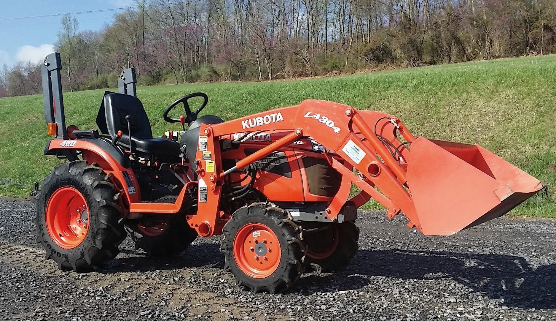 B2320
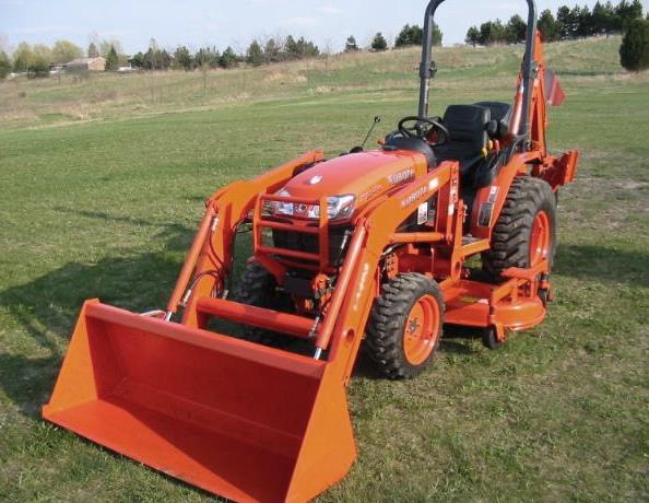 B2630
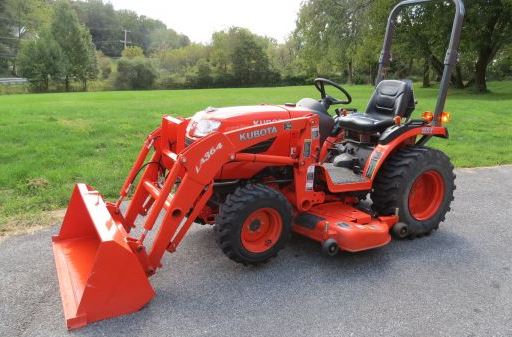 B2920
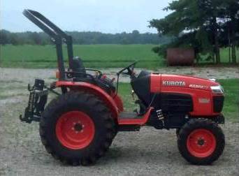 B3300SU
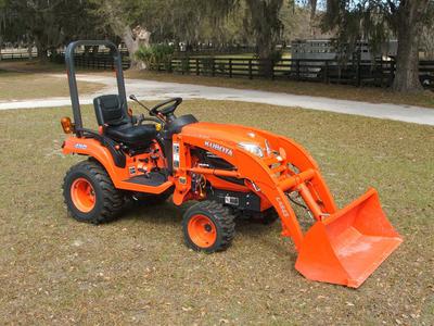 BX2360
________________________________________________________________________________________
 L245
 L260
 L275
 L285
 L305
________________________________________________________________________________________
 D662
 D722
 D750
 D782
 D850
________________________________________________________________________________________
_______________________________________________________________________________________
 LA302
 LA304
 LA340
 LA344
 LA351
________________________________________________________________________________________
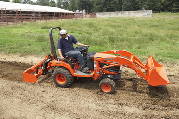 BX2660
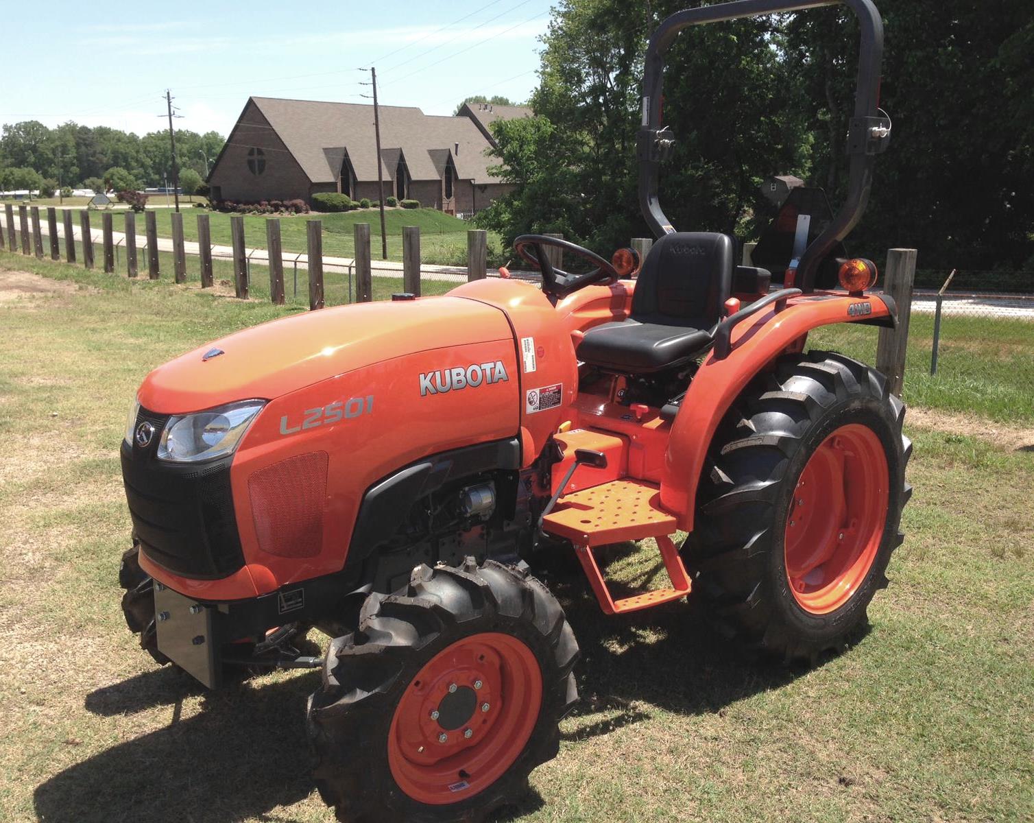 L2501
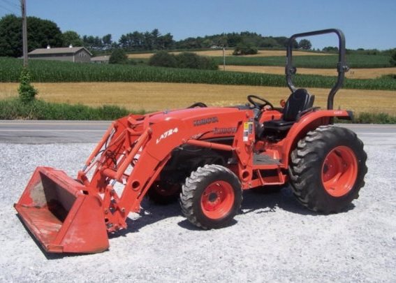 L3240
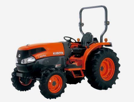 L3540
 L3940
________________________________________________________________________________________
 D902
 D905
 D950
 D1005
 D1100
________________________________________________________________________________________
 B1630
 BF400
 BF400G
 LA181
 LA203
________________________________________________________________________________________
 LA211
 LA243
 LA271
 LA272
 LA301
________________________________________________________________________________________
 L175
 L185
 L210
 L225
 L235
________________________________________________________________________________________
 D1105
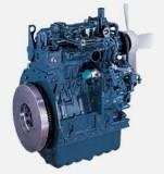 D1503
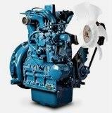 D1703
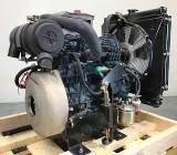 D1803
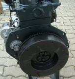 V1200
________________________________________________________________________________________
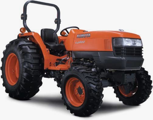 L4400
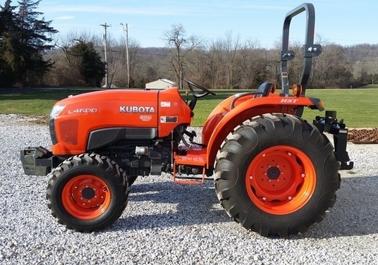 L4600
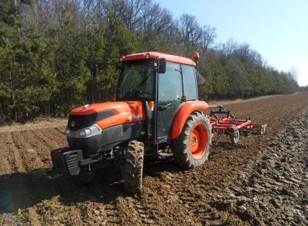 L5040
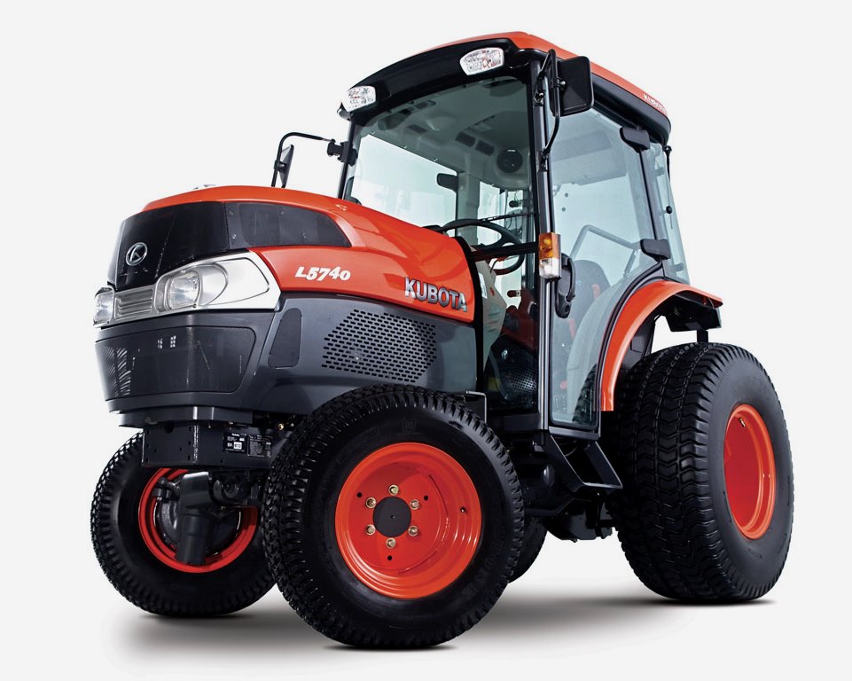 L5740
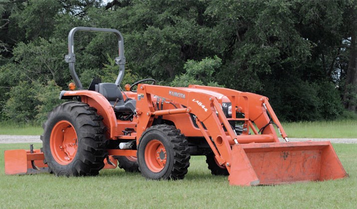 MX4700
________________________________________________________________________________________
 LA352
 LA364
 LA401
 LA402
 LA403
________________________________________________________________________________________
 LA434
 LA463
 LA481
 LA482
 LA504
________________________________________________________________________________________
 V1205
 V1305
 V1505
 V2203
 V2403
________________________________________________________________________________________
 B2710
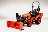 BX23S
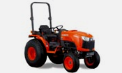 B3350
 BX1880
 L4701
________________________________________________________________________________________
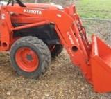 LA513
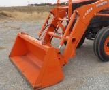 LA514
 LA524
 LA525
 LA534
________________________________________________________________________________________
 LA555
 LA680
 LA681
 LA682
 LA703
________________________________________________________________________________________
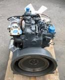 Z482
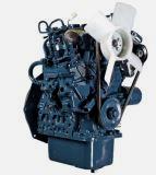 Z602
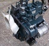 Z750
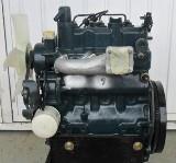 Z1100
 Z1300
________________________________________________________________________________________
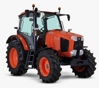 M100GX
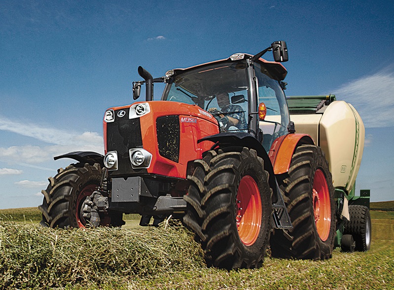 M135GX
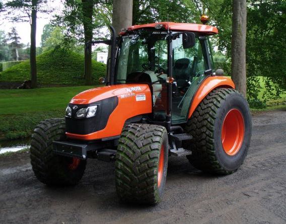 M6040
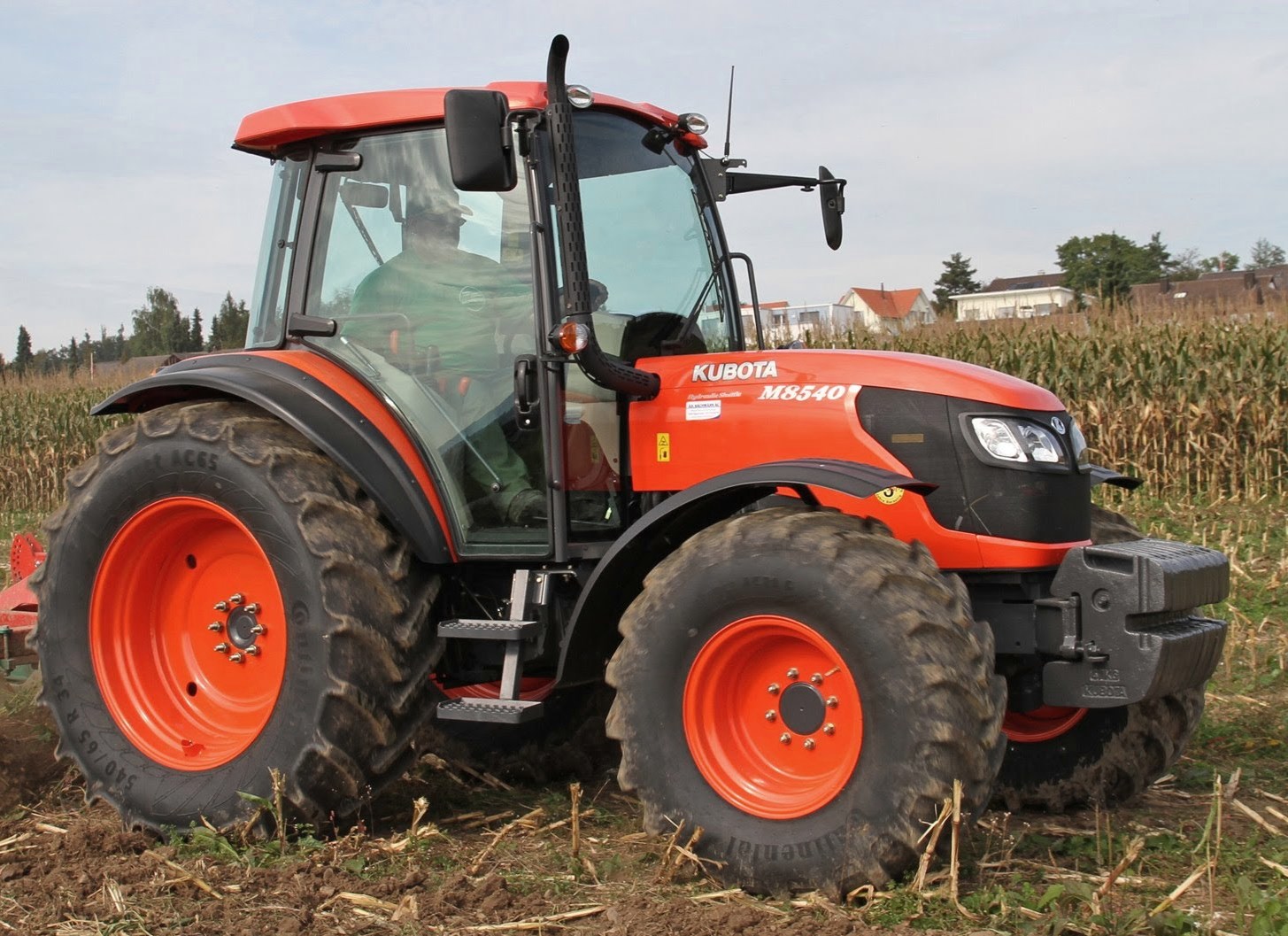 M8540
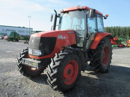 M95X
________________________________________________________________________________________
 LA714
 LA723
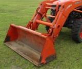 LA724
 LA764
 LA765
________________________________________________________________________________________
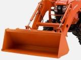 LA805
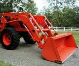 LA844
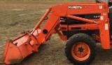 LA852
 LA853
 LA854
________________________________________________________________________________________
 M5-091
 BX2680
 MX5200
 BX2380
 L3901
________________________________________________________________________________________
 LA1002
 LA1055
 LA1065
 LA1153
 LA1154
________________________________________________________________________________________
 LA1251
 LA1301S
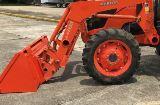 LA1353
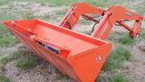 LA1403
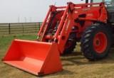 LA1601S
________________________________________________________________________________________
 LA1854
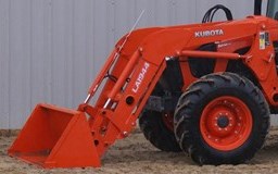 LA1944
 LA1953
 LA2253
 LM2605