________________________________________________________________________________
Kubota B2410, B2710, B2910, B7800 - HST Transmission
Kubota B2410, B2710, B2910, B7800 -
Hydrostatic Transmission System
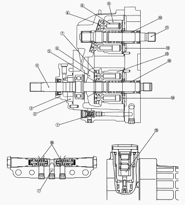
1 - Charge Relief Valve, 2 - Charge Pump, 3 - Charge Pump Case, 4 - Pump
Shaft, 5 - Variable Swashplate, 6 - Thrust Collar, 7 - Retainer Plate, 8
- Piston, 9 - Cylinder Block (Motor), 10 - Needle Bearing, 11 - Motor
Shaft, 12 - Valve Plate (Motor), 13 - Cylinder Block (Pump), 14 - Valve
Plate (Pump), 15 - Neutral Valve, 16 - Check and High Pressure Relief
Valve
Check and High Pressure Relief Valve
The check and high-pressure relief valve consists of pressure poppet,
check valve seat, relief valve spring, spring guide and check valve
spring. The valve is used to prevent an overload that would happen at a
quick start, sudden stop or even during usual running. This valve
doubles as a check valve. The check and high-pressure relief valves are
laid out facing each other as shown in the figure.
In neutral, both valves are open and charging oil enters into the main
oil circuit through the valves.
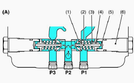
A - In Neutral (Stop): 1 - Check Valve Seat, 2 - Pressure Poppet, 3 -
Relief Valve Spring, 4 - Spring Guide, 5 - Check Valve Spring, 6 - Valve
Plug
At normal operation, the check valve in the high pressure side is closed
and it pushes and opens the another one. An excessive charge flow goes
through the charge relief valve into HST housing (B).
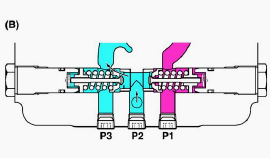
B - When Check Valve Activating (Normal Operation)
The check and high-pressure relief valve along the high-pressure line
serves as a high-pressure relief valve. If the pressure exceeds a
high-pressure limit level, the pressure poppet opens itself against the
relief valve spring (3) force and opens the valve seat that is located
between the check valve seat (1) and the pressure poppet (2). Now the
flow goes from P1 to P2 and P3 (C).
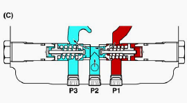
C - When High Pressure Relief Valve Activating
If the P1 pressure drops, the relief valve spring forces the valve seat
closed against the pressure. The high pressure oil at P1 does not flow
to P2 any longer. As discussed above, the check and high-pressure relief
valve protects engines, pumps, motors, gears and even the machine itself
from overload.
Front Wheel Drive System
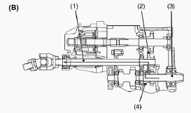
B2410: 1 - Front Wheel Drive Shaft, 2 - Shifter Gear 20T, 3 - Spiral
Bevel Pinion Shaft, 4 - Gear 13T
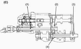
B2710, B2910, B7800: 1 - Front Wheel Drive Shaft, 2 - Shifter Gear 19T,
3 - Spiral Bevel Pinion Shaft, 4 - Gear 14T
2-wheel drive or 4-wheel drive is selected by changing the position of
shifter gear (2) with the front wheel drive lever. When the front wheel
drive lever is set to “Disengaged”, the shifter gear (2) is neutral and
power is not transmitted to the front wheel drive shaft (1). When the
front wheel drive lever is set to “Engaged”, the shifter gear (2) slides
to the right to engage with gear (4) on the spiral bevel pinion shaft
(3). Therefore, the front drive shaft is actuated to drive the front
wheels.
Kubota B2910, B7800 Hydrostatic Transmission - Cruise Control
Cruise Control Linkage
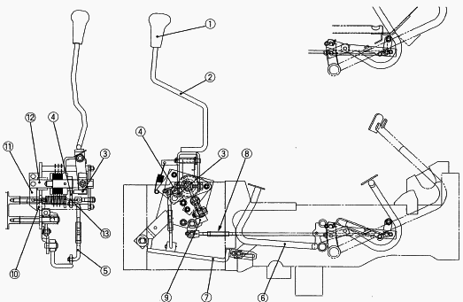
1 - Grip, 2 - Cruise Control Lever, 3 - Lever Pin, 4 - Cruise Control
Arm, 5 - Cruise Control Rod, 6 - HST Pedal, 7 - HST Pedal Lever, 8 - HST
Release Rod, 9 - Release Lever 1, 10 - Release Lever 2, 11 - Release
Arm, 12 - Cruise Control Shaft, 13 - Spring
Tilt the cruise control lever (2) to the right, and the lever pin (3) is
activated to lift the cruise control arm (4). Move the above lever
forward, and the HST pedal lever (7) rises by the cruise control rod (5)
that is coupled with the cruise control arm (4) (The HST pedal (6) is
now in the depressed position). Now the cruise control lever (2) can be
fixed (set) to a desired position through the disc (friction) and the
plate under spring (13) force. With the cruise control lever (2) set at
the center on the lever guide, the HST pedal (6) is given an allowance
by the oval hole of the HST pedal lever (7). This pedal can be stepped
further down by this allowance (This means that the machine speed can be
accelerated from a setting and that when the HST pedal is released, the
machine speed comes down to the setting).
Cruise Control Release System
This is release system of the cruise the cruise control back to neutral
automatically when brake pedals are depressed. Cruise control lever is
set with plate, friction disc by the cruise control shaft, release arm
and spring. When brake pedals are depressed, brake link pull the HST
release rod, release lever 1 and release lever 2. Afterwards, cruise
control shaft is pulled though release arm. As a result, the holding
force of cruise control lever is lost. And, cruise control lever returns
to neutrality by force of the spring and the return force of HST.
Kubota B2410, B2710, B2910, B7800 - Differential Gear
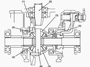
1 - Spiral Bevel Gear, 2 - Spiral Bevel Pinion, 3 - Differential Gear
Case, 4 - Differential Side Gear, 5 - Differential Pinion, 6 -
Differential Pinion Shaft
The differential gear assembly is a mechanism to provide smooth
steering. It automatically provides different optimum torques to the
right and left wheels according to road resistance and braking friction
at the wheels. The differential gear assembly is composed of the
differential case, differential pinions, differential side gears,
differential pinion shaft, spiral bevel gear, etc.
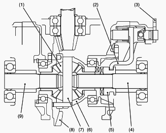
Differential Lock: 1 - Differential Pinion, 2 - Shift Fork, 3 -
Differential Lock Lever, 4 - Differential Gear Shaft, 5 - Differential
Lock Clutch, 6 - Differential Case, 7 - Differential Pinion Shaft, 8 -
Spiral Bevel Gear, 9 - Differential Gear Shaft
Kubota B2410, B2710, B2910, B7800 Differential Troubleshooting
Problem - Excessive or Unusual Noise at All Time
Improper backlash between spiral bevel pinion and bevel gear - Adjust.
Improper backlash between differential pinion and differential side gear
- Adjust.
Bearing worn - Replace.
Insufficient or improper type of transmission fluid used - Replenish or
replace.
Problem - Noise while Turning
Differential pinions or differential side gears worn or damaged -
Replace.
Differential lock binding (does not disengage) - Replace.
Bearing worn - Replace.
Problem - Differential Lock Can Not Be Set
Differential lock shift fork damaged - Replace.
Differential lock shifter mounting pin damaged - Replace.
Differential lock clutch damaged - Replace.
Problem - Differential Lock Pedal Does Not Return
Differential lock pedal return spring weaken or damaged - Replace.
Differential lock fork shaft rusted - Repair.
Kubota B2410, B2710, B2910, B7800 Tractor - Separating Engine from Clutch
Housing
Draining Transmission Fluid
Place oil pan underneath the transmission case, and remove the drain
plugs.
Drain the transmission fluid.
Reinstall the drain plug.
Fill new oil from filling port after removing the filling plug up to the
upper notch on the dipstick.
After running the engine for few minutes, stop it and check the oil
level again, if low, add oil prescribed level.
Transmission fluid capacity:
B2410 - 12.5 L, B2710 - 15.5 L,
B2910, B7800 - 14.5 L.
Hood, Side Cover and Battery Cord
Open the hood and remove the front grille. Disconnect the battery
grounding cord. Disconnect the head light connectors and remove the hood
and side covers. When disconnecting the battery cords, disconnect the
grounding cord first. When connecting, positive cord first.
Steering Wheel
Remove the steering wheel cap. Remove the steering wheel mounting nut
and remove the steering wheel with a steering wheel puller
Meter Panel and Panel Under Cover
Open the meter panel and disconnect the meter panel connector and
hour-meter cable. Then remove the meter panel. Disconnect the
combination switch connector, main switch connector, hazard switch
connector and position light switch connector. Tap out the spring pin
and remove the hand accelerator lever. Remove the panel under cover.
Fuel Tank
Disconnect the fuel hose at the fuel filter side, then drain fuel
completely. Remove the fuel tank frame stay. Disconnect the hazard unit,
starter relay and regulator connectors and remove the lead wire for fuel
gauge. Remove the fuse box. Disconnect the overflow hoses of fuel line.
Remove the tank frame with fuel tank. Disconnect the hydraulic pipes and
remove the battery stay with oil cooler. Disconnect the 2P connector and
remove the engine stop solenoid. Apply a thin coat of liquid gasket to
both surface of the engine stop solenoid.
Bi-speed Turn Cable (Bi-speed Model)
Remove the spring lock pin and loosen the lock nuts and then remove the
bi-speed turn cable.
Propeller Shaft Cover and Coupling
Loosen the clamp and slide the propeller shaft cover to the rear. Tap
out the spring pin and then slide the coupling to the rear. Apply grease
to the splines of the propeller shaft and coupling.
Universal Joint and Bearing Holder
Loosen the clamp and slide the universal joint cover to the rear. Tap
out the spring pins and then slide the universal joint to the rear.
Remove the bearing holder with propeller shaft and universal joint.
Apply grease to the splines of the propeller shaft and universal joint.
Drag Link
Remove the cotter pin and loosen the slotted nut. Disconnect the drag
link with a tie-rod end lifter from the knuckle arm.
Separating the Engine from Clutch Housing
Remove the power steering delivery pipe. Disconnect the accelerator rod.
Disconnect the three point hitch delivery pipe and suction hose at the
hydraulic pump. Disconnect the glow plug lead wire and thermo sensor
lead wire. And then disconnect the connector for alternator and starter
motor lead wire. Place the jack under the center frame. Hoist the engine
by the chain at the engine hook. Remove the engine mounting screws and
separate the engine from the clutch housing.
Kubota B2410, B2710, B2910, B7800 - Hydrostatic Transmission Adjusting
Adjusting Maximum Speed
Shorten the stopper bolt front to the position where the length of the
bolt is not touched to the HST pedal (1) even if the HST pedal is fully
depressed forward. Lengthen the length of the stopper bolt front
gradually with the HST pedal fully depressed and lengthen the one turn
from the position where the head of the stopper bolt touches the HST
pedal. Tighten the lock nut. Adjust the length of stopper bolt rear to
27 to 28 mm (1.06 to 1.10 in.).
Maximum speed with turf tire (Forward)
B2410 - 21.1 to 22.1 km/h (13.2 to 13.8 mph).
B2710, B2910, B7800 - 23.5 to 24.5 km/h (14.7 to 15.3 mph).
Maximum speed with turf tire (Reverse)
B2410 - 16.8 to 17.8 km/h (10.5 to 11.1 mph).
B2710, B2910, B7800 - 18.7 to 19.7 km/h (11.7 to 12.3 mph).
Adjusting Cruise Control Linkage
With the cruise control lever at the N position on the lever guide,
check for a gap between the lever pin and the cruise control arm. Adjust
the cruise control rod, when required, to leave no gap between them. At
the same time, make sure that there is no gap between the rear end of
the oval hole of the HST pedal lever and the pin of the HST pedal.
Finally step down the HST pedal all the way to make sure that the cruise
control lever can hold the HST pedal in place.
Adjusting Cruise Control Release Linkage
Adjust the brake pedals play first. Then adjust the HST release rod
turnbuckle to allow no gap between the release levers 1 and 2 as well as
between the release lever 2 and the release rod. Now step on one of the
brake pedals to make sure the cruise control is not released. Also step
on both the brake pedals coupled together to make sure that the cruise
control is released.
Cruise Control Lever
After adjusting the cruise control linkage, measure the force to move
the cruise control lever forward at its top (grip). If the force is not
within the factory specifications, loosen the lock nut and turn the nut
to adjust. Retighten the lock nut securely.
Kubota B2410, B2710, B2910, B7800 Tractor - Transmission Case
Neutral Holder and Neutral Holder Arm
Place parting marks on the neutral adjuster and the neutral holder arm.
Remove the neutral holder arm with neutral adjuster. Remove the screw
and pull out the neutral holder. Align the parting marks and install the
neutral adjuster and the neutral holder arm.
Charge Pump
Remove the charge pump mounting screws, and remove the charge pump
assembly from the HST housing. Take care not to damage the O-ring.
14T Gear -
Remove the external snap ring and draw out the 14T gear.
Center Section
Remove the center section mounting hex. socket head screws. Tap the
front of center section flange with a soft hammer and separate the
center section from HST housing. Cover the splines of each shaft with
thin tape to protect sealing lip. Install center section with gasket,
O-ring and valve plates in place. Valve plates may stick to the center
section but they are not fixed. Take care not to drop them. Valve plates
are not interchangeable. Valve plate of pump has two notches and the one
of motor has no.
Motor Cylinder Block and Pump Cylinder Block
Pull out the output shaft and motor cylinder block with pistons as a
unit. Slide out the pump cylinder block with pistons.
4th Gear Shaft and Spiral Bevel Pinion Shaft
Remove the spiral bevel pinion shaft with 15T-29T (B2410) or 16T-27T-32T
shifter gear, 13T (B2410) or 14T gear and shift fork. Remove the 4th
gear shaft. When installing the spiral bevel pinion shaft, be sure to
install the shims. When disassembling the spiral bevel pinion shaft, be
sure to replace the external snap ring with new one.
Bearing Holder
Remove the external snap ring and remove the 27T gear. Remove the
bearing holder mounting screws and remove the bearing holder.
2nd Gear Shaft and Middle Shaft
Remove the 2nd gear shaft with bearings. Remove the 3rd shaft assembly
and shift fork with shift rod. Remove the middle shaft and 19T gear with
bearing. When assembling the 19T gear, face the chamfer side to the
rear.
Front Wheel Drive Shaft -
Remove the external snap ring and remove the 20T shifter gear. Draw out
the front wheel drive shaft to the front.
Mid-PTO Shaft
Remove the spring and ball. Draw out the dowel pin and remove the shift
arm with shifter. Remove the oil seal and internal snap ring. Remove the
mid-PTO shaft with 11T shifter gear and bearings. Apply grease to lip
and outer of oil seal.
Kubota B2410, B2710, B2910, B7800 - Hydrostatic Transmission Service
Charge Pump
Check the charge pump housing and the gerotor assembly for scratches and
wear. If scratch or worn, replace the charge pump complete assembly.
Input Shaft
Pull out the input shaft from the case. Check the seal surface, the
bearing surface and the bearing. If the shaft is rough or grooved,
replace. If the bearing is worn, replace.
Cylinder Block Bore and Pistons
Lift all the pistons gently with the retainer plate. Check the pistons
for their free movement in the cylinder block bores. If the piston or
the cylinder block bore is scored, replace cylinder block assembly. Do
not interchange pistons between pump and motor cylinder block. Pistons
and cylinder blocks are matched. Clearance between piston and bore -
0.02 mm (0.0008 in).
Piston Slipper and Retainer Plate
Check the slipper for flatness. If rounded, replace Measure the
thickness of piston slipper. If the measurement is less than the
allowable limit, replace. Check the lubricant hole for clogging.
Thickness of slipper - 3.00 mm (0.118 in).
Cylinder Block Face
Check the polished face of cylinder block for scoring. If scored,
replace cylinder block assembly. Check the spring for breakage. If
broken, replace cylinder block assembly.
Transmission Case
Checking Bearing
Hold the inner race, and push and pull the outer race in all directions
to check for wear and roughness. Apply transmission fluid to the
bearing, and hold the inner race. Then, turn the outer race to check
rotation. If there is any defect, replace it.
Clearance between Shift Fork and Shift Gear Groove
Insert the fork into the shift gear groove and measure the clearance
with a feeler gauge. If the clearance exceeds the allowable limit,
replace it. Clearance between shift fork and shift gear groove - 0.10 to
0.35 mm (0.004 to 0.014 in).
Clearance between 13T Gear and 3rd Shaft
Measure the 13T gear I.D. with an inside micrometer, and then 3rd shaft
O.D. with an outside micrometer. Measure the O.D. of two needles in the
needle bearing with an outside micrometer. Clearance is the difference
between the gear I.D. and the sum of shaft O.D. and two needle O.D. If
the clearance exceeds the allowable limit, replace it. Clearance between
13T gear and 3rd shaft - 0.007 to 0.046 mm (0.00028 to 0.00181 in). 3rd
shaft O.D. - 21.987 to 22.000 mm (0.86562 to 0.86614 in). 13T gear I.D.
- 30.007 to 30.021 mm (1.18138 to 1.18193 in). Needle O.D. - 3.994 to
4.000 mm (0.15724 to 0.15748 in).
________________________________________________________________________________
________________________________________________________________________________________
________________________________________________________________________________________
| KUBOTA TRACTORS SPECIFICATIONS |
________________________________________________________________________________________
________________________________________________________________________________________
________________________________________________________________________________________
________________________________________________________________________________________
________________________________________________________________________________________
________________________________________________________________________________________
________________________________________________________________________________________
________________________________________________________________________________________
________________________________________________________________________________________
________________________________________________________________________________________
________________________________________________________________________________________
________________________________________________________________________________________
________________________________________________________________________________________
________________________________________________________________________________________
________________________________________________________________________________________
| KUBOTA ENGINES DATA AND SERVICE SPECS |
________________________________________________________________________________________
________________________________________________________________________________________
________________________________________________________________________________________
________________________________________________________________________________________
________________________________________________________________________________________
| KUBOTA FRONT END LOADERS |
________________________________________________________________________________________
________________________________________________________________________________________
________________________________________________________________________________________
________________________________________________________________________________________
________________________________________________________________________________________
________________________________________________________________________________________
________________________________________________________________________________________
________________________________________________________________________________________
________________________________________________________________________________________
________________________________________________________________________________________
________________________________________________________________________________________
________________________________________________________________________________________
| KUBOTA TRACTORS TROUBLESHOOTING | ||||
| L235 | L2501 | L2550 | L275 | L3110 |
| L3301 | L35 | L3710 | L3901 | L4310 |
| L5030 | M4700 | M5700 | M6040 | M6800 |
| M8200 | M8540 | M9000 | MX5100 | MX5200 |

 SPECIFICATIONS
 LOADERS
 ENGINES
 MAINTENANCE
 PROBLEMS
 B1241
B1241 B1600
B1600 B1700
B1700 B1750
B1750 B21 Backhoe
 B2150
B2150 B2301
B2301 B2320
B2320 B2530
B2530 B26 Backhoe
 B2601
B2601 B2650HSD
 B3030
B3030 B3350
B3350 B6000
B6000 B6100
B6100 B6200
B6200 B7000
B7000 B7001
B7001 B7100HST
 B7200
B7200 B7500
B7500 B7510
B7510 B7800
B7800 B8200HST
 BX1880
 BX2200
 BX2230
 BX2350
 BX2370
 BX23S
BX23S BX25 TLB
 BX2660
 BX2680
 F3680
F3680 L175
L175 L185
L185 L210
L210 L225
L225 L235
L235 L245
L245 L260
L260 L275
L275 L285
L285 L305
L305 GR2120
 L1501
L1501 L2350
L2350 L2550
L2550 L2800
L2800 L3010
L3010 L3200HST
 L3301
L3301 L3560
L3560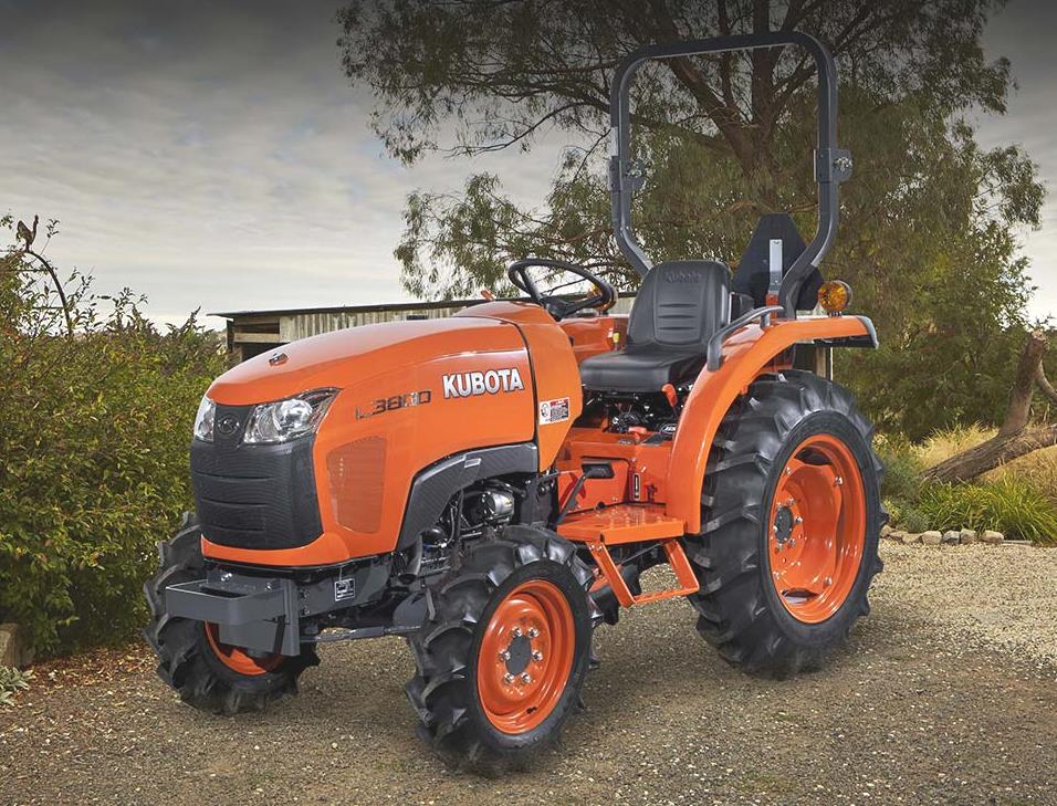 L3800
L3800 L4701
L4701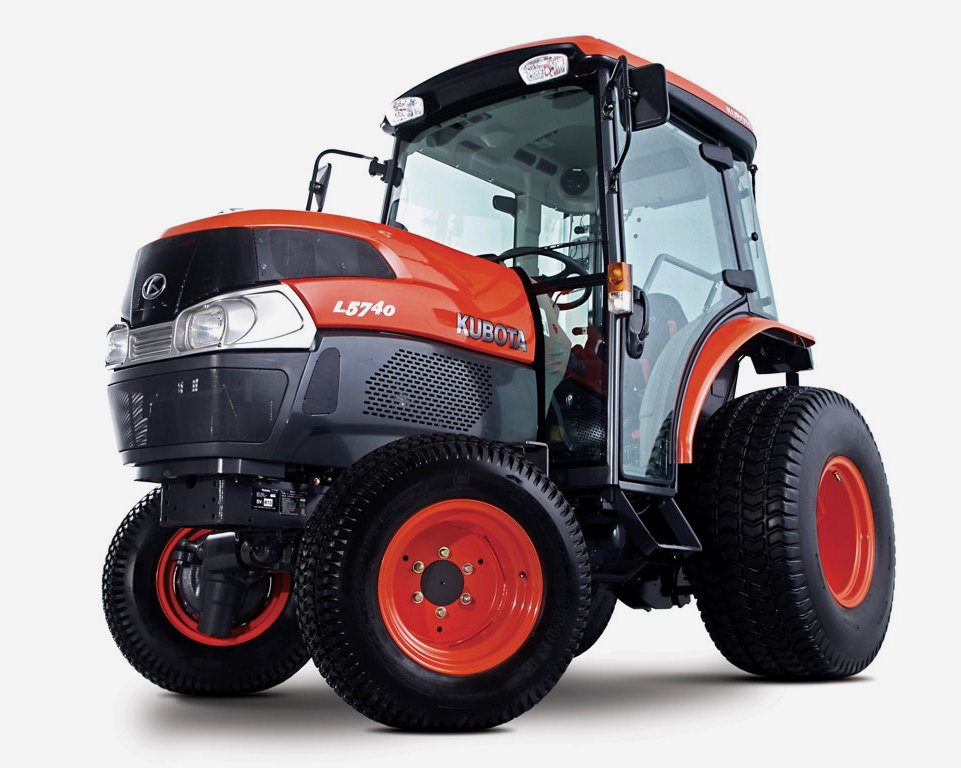 L5740
L5740 M5-091
 M5-111
 M6060
M6060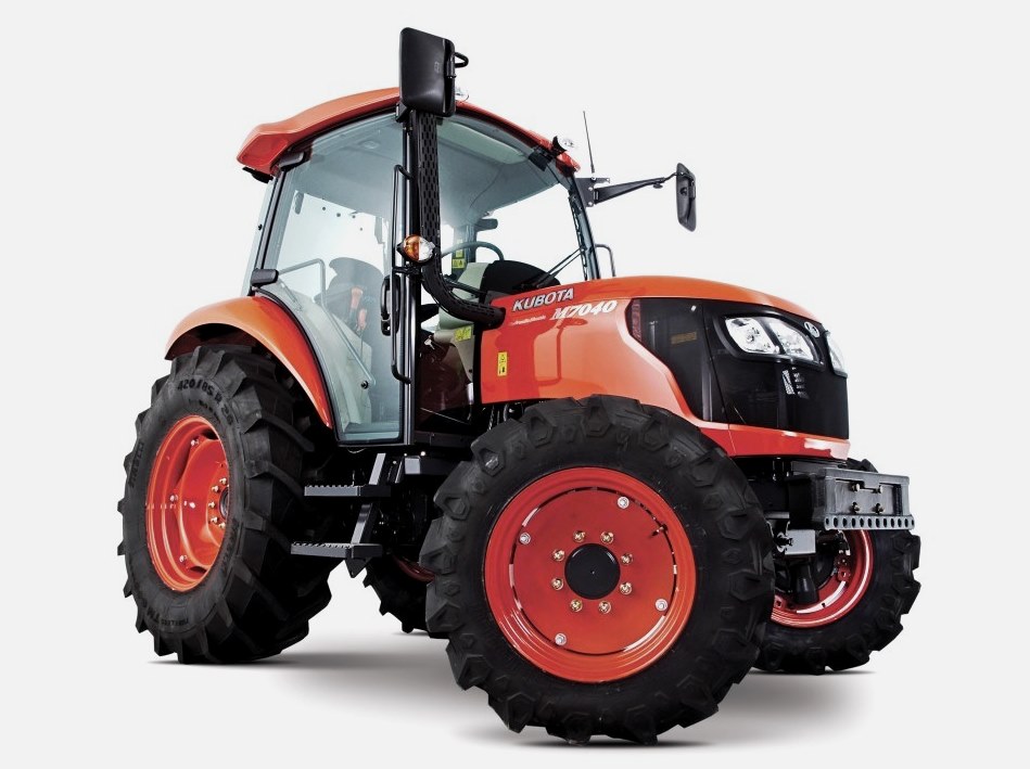 M7040
M7040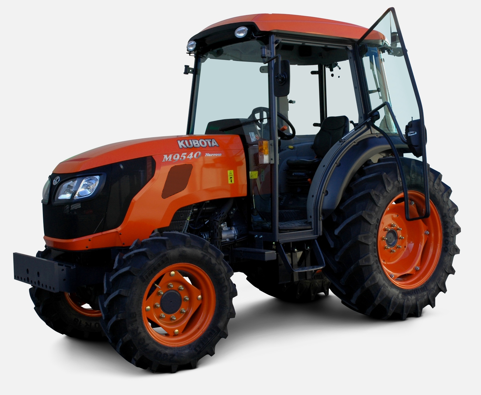 M9540
M9540 M9960
M9960 MX5100
 D662
D662 D722
D722 D750
D750 D782
D782 D850
D850 D902
D902 D905
D905 D950
D950 D1005
D1005 D1100
D1100 D1105
D1105 D1503
D1503 D1703
D1703 D1803
D1803 V1200
V1200 V1205
V1205 V1305
V1305 V1505
V1505 V2203
V2203 V2403
V2403 Z482
Z482 Z602
Z602 Z750
Z750 Z1100
Z1100 Z1300
Z1300 B1630
B1630 BF400
BF400 BF400G
 LA181
LA181 LA203
LA203 LA211
LA211 LA243
LA243 LA271
LA271 LA272
LA272 LA301
LA301 LA302
LA302 LA304
LA304 LA340
LA340 LA344
LA344 LA351
LA351 LA352
LA352 LA364
LA364 LA401
LA401 LA402
LA402 LA434
LA434 LA463
LA463 LA481
LA481 LA482
LA482 LA504
LA504 LA513
LA513 LA514
LA514 LA524
LA524 LA525
LA525 LA534
LA534 LA555
LA555 LA680
LA680 LA681
LA681 LA682
LA682 LA703
LA703 LA714
LA714 LA723
LA723 LA724
LA724 LA764
LA764 LA765
LA765 LA805
LA805 LA844
LA844 LA852
LA852 LA853
LA853 LA854
LA854 LA1002
 LA1055
 LA1065
 LA1153
 LA1154
 LA1251
 LA1301S
 LA1353
 LA1403
 LA1601S
 LA1854
 LA1944
 LA1953
 LA2253
 LM2605